Anycubic Kossel Linear Plus 3D printer kit
Overview
I had been sitting on the fence for a while regarding whether or not to buy a 3D printer. The cost versus benefit somehow did not strike me as very interesting, and I had been relying on online printing services the few times I needed to print a custom part. I moved on, mostly towards the CNC world after I got my Shapeoko. CNC is fantastic, but not very convenient to make 3D parts with lots of of curved areas and hollows inside them. So I got motivated to take a second look at 3D printing, to make hybrid CNC+3Dprinted projects and leverage the best of both worlds.
On the Shapeoko forum, I heard about the 250$ AnyCubic Kossel Linear Plus delta-style printer kit, and decided to give it a go, on a hunch. This page captures various notes from my initial experience with this 3D printer, and 3D printing in general.
- Overview
- Synoptic
- Assembly
- Homing to endswitches
- Under the hood
- Support
- Autoleveling
- Test print
- Slicer
- Material install
- First print
- Printing mods
- Wood PLA
- Bed adhesion options
- Infill
- Initial calibration tests
- Firmware backup & restore
- Migrating to Marlin 1.1.9 firmware
- Re-calibrating with Marlin 1.1.9
- Lithophane…and ringing
- Vase mode
- Nozzle trouble
- Upgrades
- Misc
- Conclusion
Synoptic
As often when discovering a new tool/hobby, it’s easy to get overwhelmed at first by the many terms involved. I captured my own view below of the various elements involved:
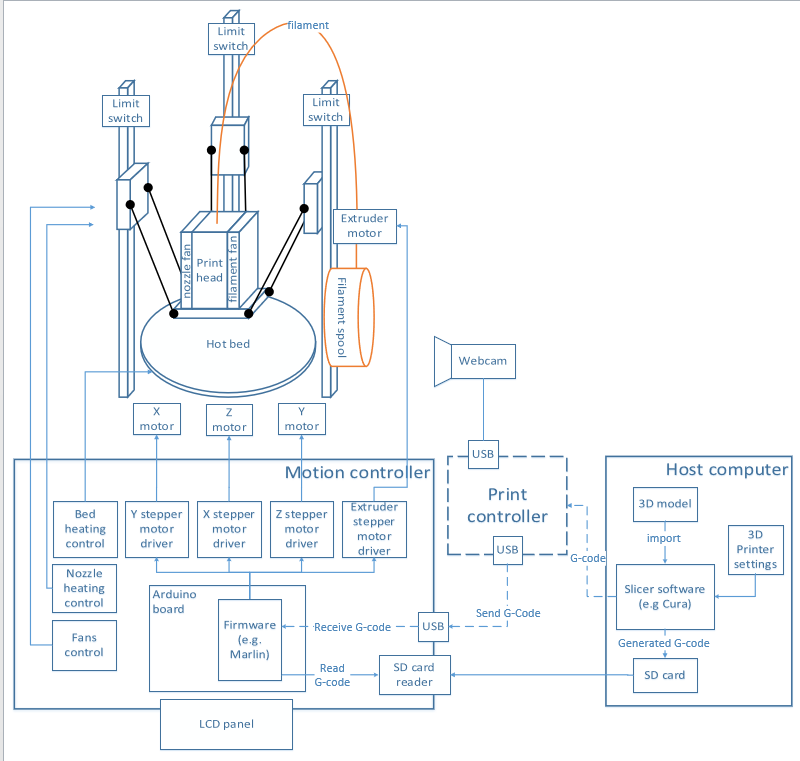
- At the beginning of the story is a 3D model file (usually in STL format)
- This 3D model is then processed by a software tool called a slicer: it takes the 3D model as input and computes required movements of the printing head to print the model, slice by slice.
- so the slicer needs to know the type/size/geometry of the target printer
- and it also takes a bunch of input parameters from the user, for example the printing speed and slice thickness.
- The output of the slicer is a G-code file, that contains (more or less) standardized commands that 3D printers can understand.
- The G-code can be fed to the printer by two means:
- copying the G-code file to a removable media (SD card in the case of the Kossel)
- sending the G-code instruction flow from a print controller (which can be the host machine itself, or another computer, typically as Raspberry Pi)
- In the printer, a controller board (a TriGorilla board in the stock Kossel kit) runs a firmware (Marlin in the case of the Kossel) that interprets G-code instructions, and controls the various devices accordingly:
- three stepper motors controlling the position of the printing head
- the heater bed
- the print head nozzle and its temperature
- the print head filament fan
- the print head extruder fan
- the endswitches on each axis
- an LCD panel with a rotary knob, implementing user menus.
- The three vertical rails are labelled “X”, “Y”, and “Z”. I think they should rather be named “A/B/C” or whatever naming not directly related to “X/Y/Z”, because due to the (delta) nature of this printer, all three axis need to collaborate to produce any specific movement in the X, Y or Z direction. From a printing/model standpoint, the bed surface is the X/Y plane, (X being the left/right direction and Y being the front/bottom direction), and the Z direction is vertical.
- an extruder motor feeds the filament from a spool, into the printing head extruder and nozzle, where it melts and gets deposited on the layer being printed.
- the first layer of the printed model is laid on the bed of the printer, which has an embedded heating mechanism. This is because the filament will adhere much better when the bed is hot, and this is crucial
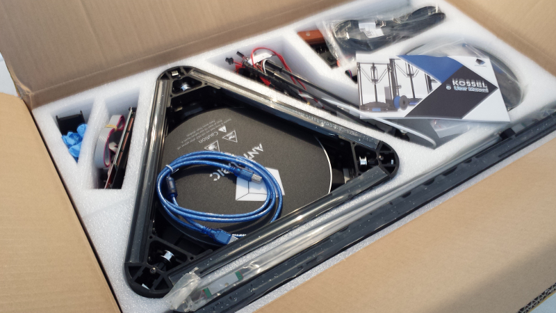
Assembly
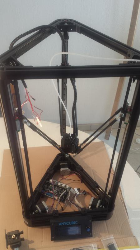
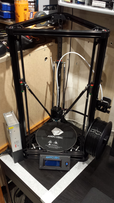
The first feeling while opening the box was positive, everything is packed neatly:
Some people say it takes an hour to assemble the machine. It probably does when you have assembled one before, but on the first run…it took me the best of an afternoon, to do everything carefully.
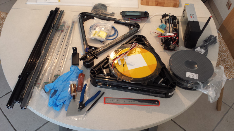
The user manual is quite clear (unusually so for a chinese product), but watching the assembly steps video from AnyCubic on Youtube beforehand helped clarify things. Below are a few snaphots and some feedback from the assembly process.
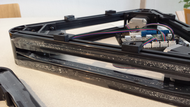
First sign of sub-par quality control: the protection tape on all rails was littered with small metal chips. A very unpleasant sight, as metal chips near electronics is the LAST kind of things I wanted to worry about. So, I first started by carefully removing these protections to avoid most of the chips falling elsewhere, and then vacuumed every single part VERY thoroughly before proceeding.
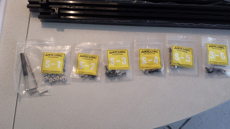
The mechanical parts required for each assembly step are stored in separate bags, which is very nice. Each bag contained 1 spare part, also a very good idea.
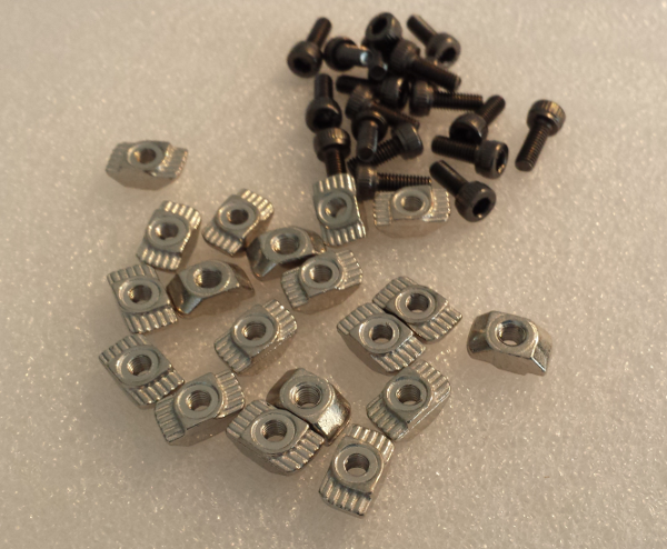
The whole mechanical assembly relies on multiple of these small T-nuts, to be inserted in the rails. Simple and efficient. However, at this point I got a second “chinese quality control” vibe, when I discovered that among the provided Allen keys, NONE of them was the right size for these T-nuts… Luckily I had one of the proper size at home, but still…not quite serious.
Minor thing: removing the plastic protection from the rails takes a bit of time in places, since they put the protection on and THEN assembled the corner parts on top…
The X/Y/Z rails look decent:
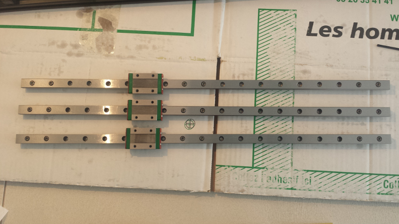
Mine had these small rubber things inserted in the holes at each end, to prevent the sliding part from falling: while it is a good thing, the instructions do not mention them, and they NEED to be removed or they will interfere with the movements. The rails were quite greasy (good thing), so the provided pair of gloves did help.
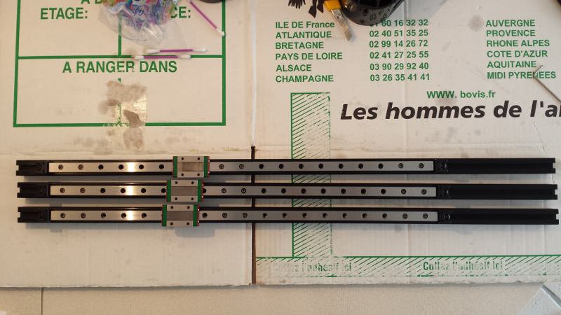
The three rails, assembled onto the vertical beams:
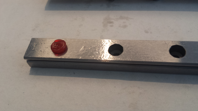
Yet another sign of poor quality control: one of the three belt tensioners was all wrong, and no spare provided on this specific part, so I had to use pliers to force this ugly tensioner back into the same shape as the other two. It turned out to work fine in the end, but well…
Frame assembled, halfway there:
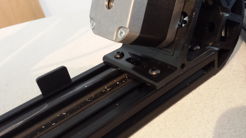
NOTE: I noticed that the pulleys on the X/Y/Z motors are assembled incorrectly: each pulley has two set screws, and the pulley should normally be attached such that at least one of the set screws pushes on the FLAT part of the motor shaft. This was not the case on either of the pulleys. I figured I would leave this as is, and come back to it after a while if I noticed signs of belt slip.
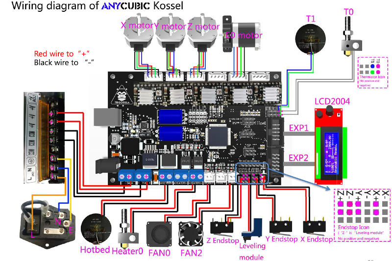
Then came wiring. Every wire is labelled, and the instructions are clear, so all good there. For my own convenience I log the wiring (copied from the user manual) here:
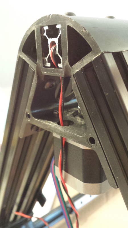
Minor grudge: the endswitch wires exit under the bottom of the beams, and the machine will rest on the base surface with very little height margin for the wire:
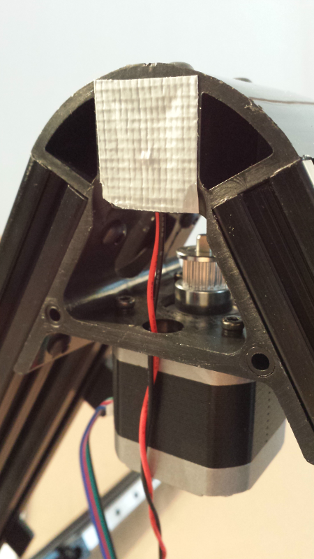
I figured this was not very good, and could wear out/damage the wire when the machine is moved, so out of extra carefulness I added a piece of untearable tape on the bottom of each foot:
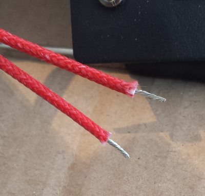
Most wires have soldered endpoints, but two of them didn’t (so I added solder, as I did not to wait to take any risk on the quality of connection of these wires, which get squished by the connector screw)
All done:
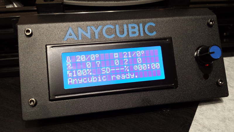
After inserting the provided SD card, it was time to power on for the first time:
Homing to endswitches
Before starting a job, the machine will go to its home/reference position, which is when the three carriages are at the top of their rail, right where to come in contact with the endswitches enough to trigger them. So I tried just this…and only Z axis moved, while X and Y stayed idle. Which ended up in the printing head crashing against the Z-rail…and I hit the power button as quickly as I could. Bummer. So I started investigating what was wrong, which gave me the opportunity to take a look at the debug traces that the controller board spits on the USB link.
Under the hood
The controller board (more specifically its Marlin firmware) provides a serial interface at 115200 bauds, over USB.
I used the Arduino IDE to capture the first traces, but any serial communication terminal will do. In the Arduino IDE, select board type Arduino Mega or Mega 2560, select the appropriate COM port that the host PC attributed to the serial link, open Serial Monitor and change speed to 115200 bauds.
I got this:
		start
		echo: External Reset
		Marlin 1.1.0

		echo: Last Updated: 2016-12-06 12:00 | Author: (ANYCUBIC PLUS, 2017/9/18)
		Compiled: Oct 13 2017
		echo: Free Memory: 3329  PlannerBufferBytes: 1168
		Error:EEPROM checksum mismatch
		echo:Hardcoded Default Settings Loaded
		echo:Steps per unit:
		echo:  M92 X80.00 Y80.00 Z80.00 E96.00
		echo:Maximum feedrates (mm/s):
		echo:  M203 X200.00 Y200.00 Z200.00 E200.00
		echo:Maximum Acceleration (mm/s2):
		echo:  M201 X3000 Y3000 Z3000 E3000
		echo:Accelerations: P=printing, R=retract and T=travel
		echo:  M204 P3000.00 R3000.00 T1500.00
		echo:Advanced variables: S=Min feedrate (mm/s), T=Min travel feedrate (mm/s), B=minimum segment time (ms), X=maximum XY jerk (mm/s),  Z=maximum Z jerk (mm/s),  E=maximum E jerk (mm/s)
		echo:  M205 S0.00 T0.00 B20000 X5.00 Y5.00 Z5.00 E5.00
		echo:Home offset (mm)
		echo:  M206 X0.00 Y0.00 Z0.00
		Auto Bed Leveling:
		echo:  M420 S0
		echo:Endstop adjustment (mm):
		echo:  M666 X0.00 Y0.00 Z0.00
		echo:Delta settings: L=diagonal_rod, R=radius, S=segments_per_second, ABC=diagonal_rod_trim_tower_[123]
		echo:  M665 L271.50 R135.40 S80.00 A0.00 B0.00 C0.00
		echo:Material heatup parameters:
		echo:  M145 S0 H180 B70 F0
		  M145 S1 H240 B110 F0
		echo:PID settings:
		echo:  M301 P22.20 I1.08 D114.00
		echo:Filament settings: Disabled
		echo:  M200 D3.00
		echo:  M200 D0
		echo:Z-Probe Offset (mm):
		echo:  M851 Z-15.90
		echo:SD card ok
The Error:EEPROM checksum mismatch was a bit worrying, but turned out to be due to the fact that the controller still had factory parameters: this error disappeared after the first successful bed leveling (more on this below). I wanted to figure out if there was something mechanically wrong with the X and Y axis that were not moving, so I needed a way to send unitary G-code commands manually. I installed the Pronterface program, which does way more than this, but turned out to work first time for sending these G-code commands.
As a memo to myself, I capture the manual G-code commands I used:
First G17 to select the XY plane orientation
>>> G17
SENDING:G17
Then G21 to switch to mm mode:
>>> G21
SENDING:G21
Then G91 to use relative coordinates mode:
>>> G91 (RELATIVE coords)
SENDING:G91
First a safe command that is supposed to do nothing (i.e. move by 0 mm on X and 0 mm on Y):
>>> G0X0.0000Y0.0000
SENDING:G0X0.0000Y0.0000
No movement, so far so good. Then I tried to move Y axis by 1 mm:
>>> G0X0.0000Y1.0000
SENDING:G0X0.0000Y1.0000
And saw the printer head indeed move by 1mm to the right. I continued sending similar commands:
>>> G0X0.0000Y1.0000
SENDING:G0X0.0000Y1.0000
>>> G0X0.0000Y1.0000
SENDING:G0X0.0000Y1.0000
>>> G0X0.0000Y5.0000
SENDING:G0X0.0000Y5.0000
But after a while I got this:
>>> G0X0.0000Y-5.0000
SENDING:G0X0.0000Y-5.0000
echo:endstops hit:  X:233.05 Y:233.05
The printer head was still in the middle, and X and Y carriages where nowhere near their endstops…with no clue as to the root cause of this, I decided to try AnyCubic’s support.
Support
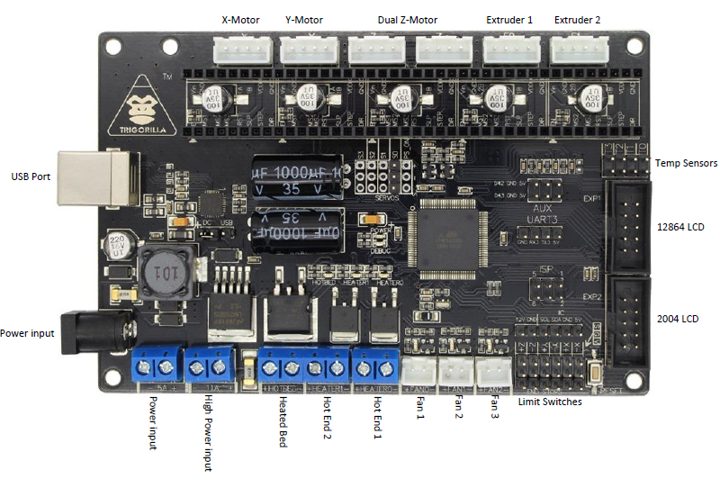
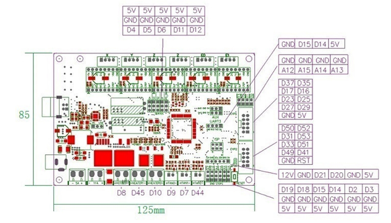
I used AnyCubic’s website to send an email to support, and honestly I expected to never get an answer back, or to get a very poor answer. I was very wrong. I sent the mail on a Sunday, and got a helpful reply Monday afternoon. The answer copy/pasted a zoomed-up version of the header pinout on the controller board, which got me to have a second look at the manual…and discovered that if indeed the pinout in the corner is correct, the picture showing where the leads go is poor and I had plugged the X and Y endswitchs connectors shifted by one row. Doh !
I re-plugged them in the right place,
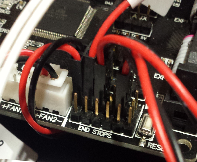
got a successfull homing, and was happy to see that it IS possible to get good support, in English, from a chinese company. Who knew…
Autoleveling
This next step is quite important to get the printer in working order. Mechanical and assembly tolerances are such that the machine must be calibrated so that it knowns exactly where the surface of the hotbed is, in Z dimension, from its homing position. This can be calibrated manually, but the Kossel comes with a very nice auto-leveling feature that automates this, by using a contact sensor to be mounted on the print head. It seems I have what AnyCubic calls “version 2” of the leveling sensor. It snaps in place with a magnet, very convenient:
Once installed and connected, the procedure is quite simple:
- From the
Autoleveling Bedmenu, selectMeasure Z Pos. The machine will home, then descend towards the hotbed, probe multiple points on this surface, then home again, and reset. Here it is in action:
-
Then, from
Autoleveling Bed, selectPrepare Levelingmenu, andBegin Leveling. The machine will home, probe multiple points on the surface again, home, then probe one final point. -
The previous two steps result in a new Z-offset being computed by the controller. The final step is to store it: in the
Autoleveling Bedmenu, selectPrepare Levelingthen click onZ Offsetand turn the knob to adjust Z offset to the same value as “New Z Offset” being dispayed. Then clickStore: the machine will home, bed leveling is now complete !
Since what the procedure does is calibrate the geometry of the bed surface, the procedure should be performed again anytime something may have moved slightly, e.g. after changing the hotbed, or moving the machine around to a new location.
Test print
The manual advises to do a test print, by using the Print from SD card menu and selecting the test file. It turns out the provided SD card I got with the machine only contained STL examples files, not a single G-code file in sight, so either the manual is wrong, or the SD Card is wrong. So, this was a good time to learn how to produce G-code from a 3D Model.
Slicer
There are multiple choices out there for the slicer software, I choose the easy route and went for the de-facto standard: Ultimaker Cura. I installed Cura, but did NOT launch it yet. By default, the version I used did not have a profile for the Kossel, so I derived one from this one, which I backed-up here. Note: I updated it it slightly, removing the “ID” parameter, otherwise I got format errors with Cura 3.5.x.
- On Windows, the
anycubic_plus.deffile goes inC:\Program Files\Ultimaker Cura 3.x\resources\definitions - On Linux, put the json file under
~/.local/share/cura/3.x/definitions
Then when launching Cura for the first time, the printer setup wizard will pick up the Kossel profile file, and one can select it from the list of available printers (AnycubicLinear Plus in the Other section)
Cura is very simple to use:
- load a 3D model (e.g. STL file)
- move/scale/rotate it as appropriate
- adjust printing parameters
- Layer Height: thicker layers print faster but are more visible, thinner layers take longer but are less visible. Typically 0.2mm by default (average quality), 0.1mm for fine prints, 0.35mm for quick&dirty prototypes.
- Shell thickness params: thickness of the solid outer walls of the 3D object, beyond which the selected infill pattern will be applied. Defaults to 0.8mm.
- Infill density and pattern: how much material is used inside the 3D object, from 0% (hollow inside) to 100% (solid), and which geometry pattern is used to create the inside structure.
- Filament temperature: depends on the filament material, typically around 200°C for PLA.
- bed temperature: depends on the filament material, to ensure the first layer sticks.
- enable retraction option: if activated, will pull the filament back when travelling across printed sections, to avoid unexpected trails of filament across the layers.
- print speed, in mm/s, of the printer head. 50mm/s is a base value, lower value can be required to improve print quality or deal with difficult sections of the print (overhangs…)
- support option will add pillars of material under any part of the 3D model that overhangs too much (basically, anything with an angle greater than 45° versus vertical). Requires manual removal of these support parts after printing.
- build plate adhesion type: none, brim, skirt, or raft. See images down below.
Cura has advanced and export modes that allow to control sub-parameters for each of these things, but no need to rush into complexity too early.
Material install
Nothing special there, I first used the spool of PLA provided with the machine, did a fresh diagonal cut of the filament, inserted it in the extruder motor and then pushed it manually through the guide tube towards the extruder.
First print
I used one of the STL files provided on the SD card shipped with the machine, sliced it in Cura to produce a corresponding g-code file, then used print from SD Card menu on the LCD panel, and launched the print for the first time (which is a slightly scary moment…)
As the manual suggests, during the first moments of the print I adjusted the Z (using Z+0.1 and/or Z-0.1 in the Autoleveling menu), and this was not quite easy to get right since I had no idea what a “good” print was supposed to look like, and the pictures from the manual are not so obvious. After a few trial and error tests, I got it right (i.e. nice clean “tube” of filament sticking to the hot bed), and the print proceeded with no issue.
Printing mods
Since I knew I was going to waste a lot of PLA during the first tests, I went ahead and tried to print things that would be useful if printed successfully. The inevitable stop on the journey of the 3D printer newbie is to print all kinds of gadgets to mod the printer itself. It’s a good way to learn while not caring too much about mistakes/poor results.
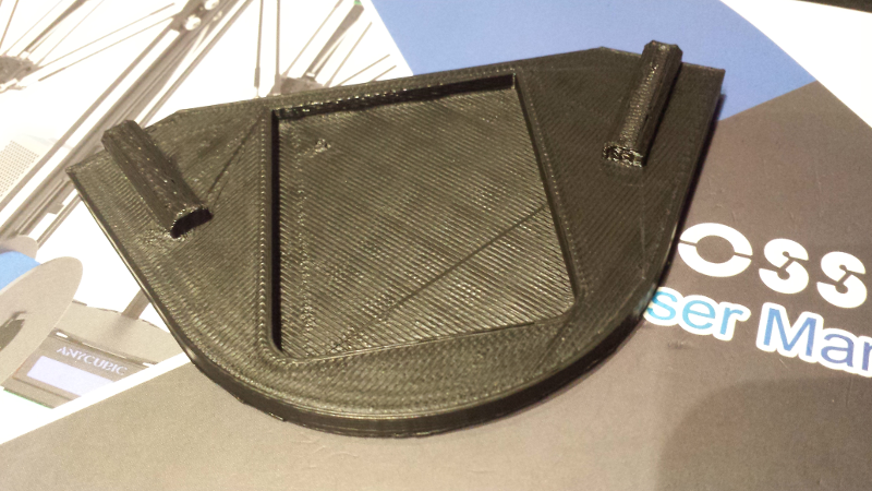
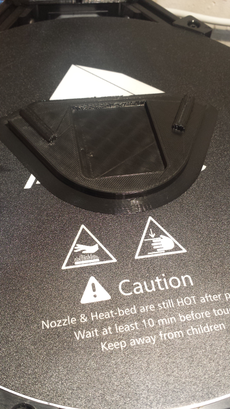
I started by printing caps for the bottom and top corners of the machine: it gives the machine a more “finished” look, while protecting motors and pulleys from dust or any other foreign object. I loaded the 3D model of the bottom cover from Thingiverse in Cura, and then used these settings to generate the G-code:
- layer height 0.2mm
- shell thickness 0.8mm
- infill 20%
- speed 60mm/s
- cooling enabled
- built plate adhesion: Brim
I loaded the G-code on the SD card, selected “print from SD Card” on the LCD panel, and launched the print. It came out surprisingly good for a first real part:
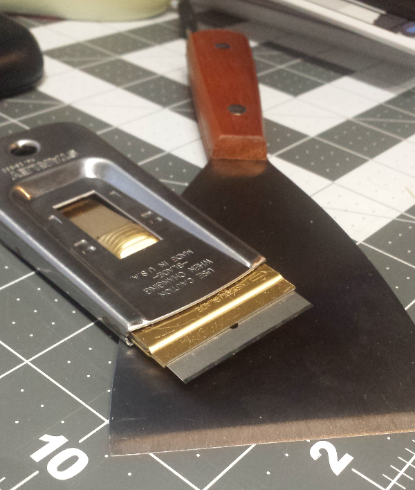
After letting it cool down, I slipped a razor blade edge under the edge, then used the scraper provided in the Kossel kit to pry the object away from the surface, gently.
It went easily. So I proceeded to print the other two covers:
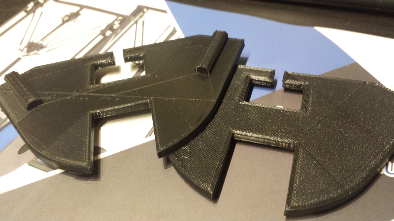
NOTE: one small defect is the diagonal line, that corresponds to a moment when the printing head travelled across the layer while not printing, but somehow still leaved a trail of PLA despite the “retraction” option in Cura. I will have to investigate how to fix this.
And another good surprise, they snapped in place just right, so there did not seem to be any obvious issue with the machine calibration.
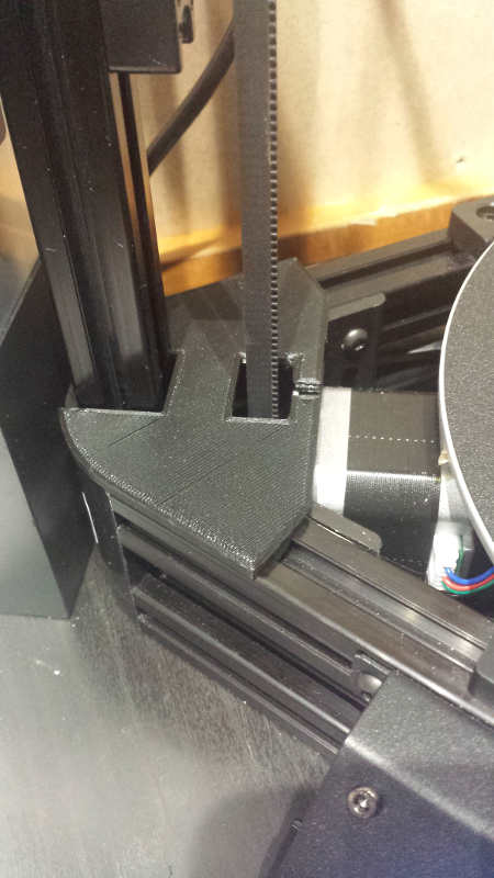
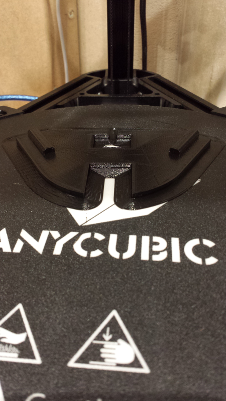
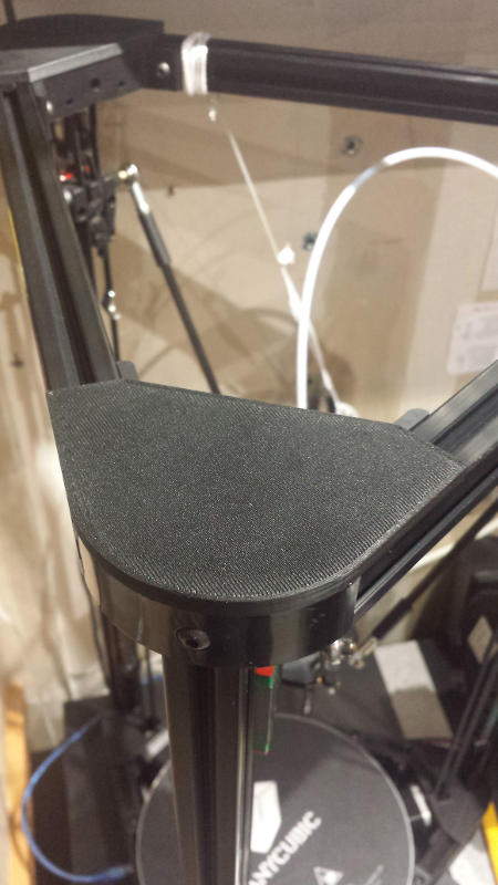
I then printed the top caps:
and installed them:
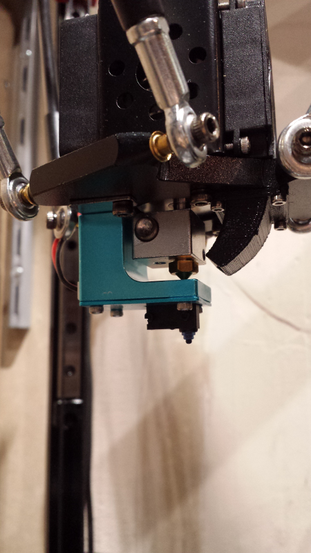
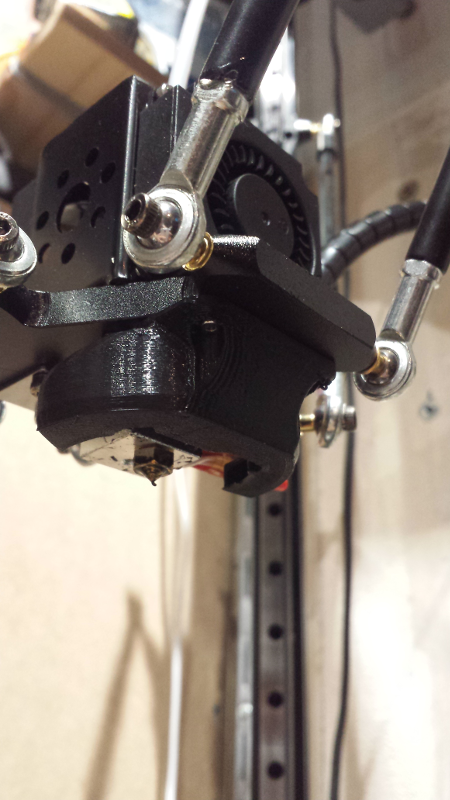
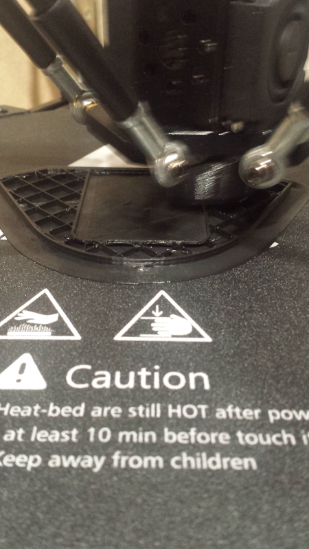
and finally printed a custom fan shroud (that spreads the air flow from multiple directions, which the stock one does not, and this helps the quality of the prints)
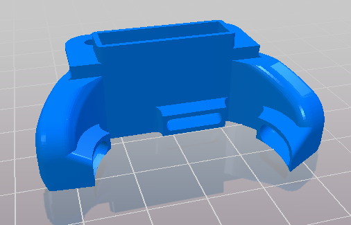
and installed it under the printing head:
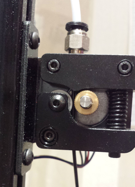
I then printed a knob to go on the extruder motor shaft, for easier manual move of the filament (e.g. when changing filament spool)
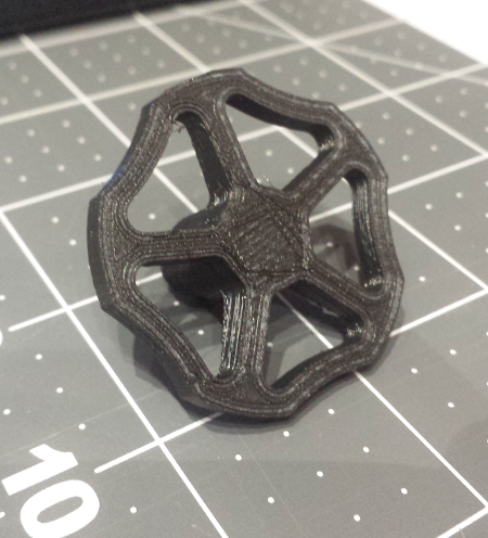
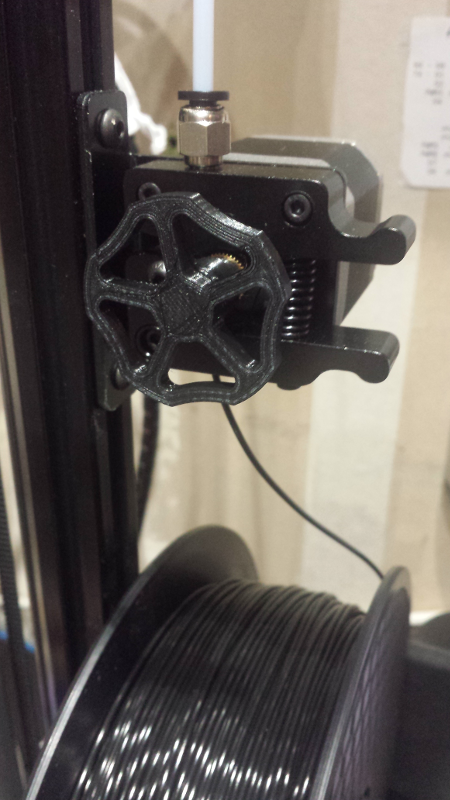
It looks better that the naked shaft, and makes extruder movements (especially retraction moves) more obvious.
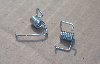
I tried these dampener feet too:
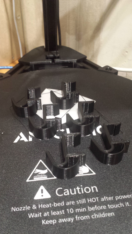
They were printed at 0.3mm res, 60mm/s, 20% infill. I installed them…and got a bad feeling. I think they are too flexible, and while doing a test print with this setup, I could see the machine vertical rails wobbling a bit too much for my taste. Anyway, I decided to get rid of them, and go for something much simpler: I reused the protection foam that came with the machine, and manually cut three pieces in the shape of the machine’s feet/corners, using the top covers as a rough template:
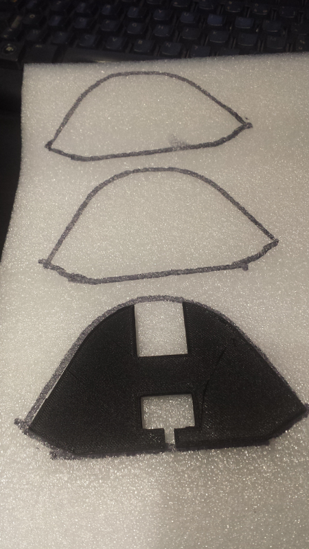
I used double-sided tape to hold them in place under the feet of the machine, and it turned out that they work perfectly: they do dampen vibrations, but are stiff enough to avoid oscillations of the whole machine.
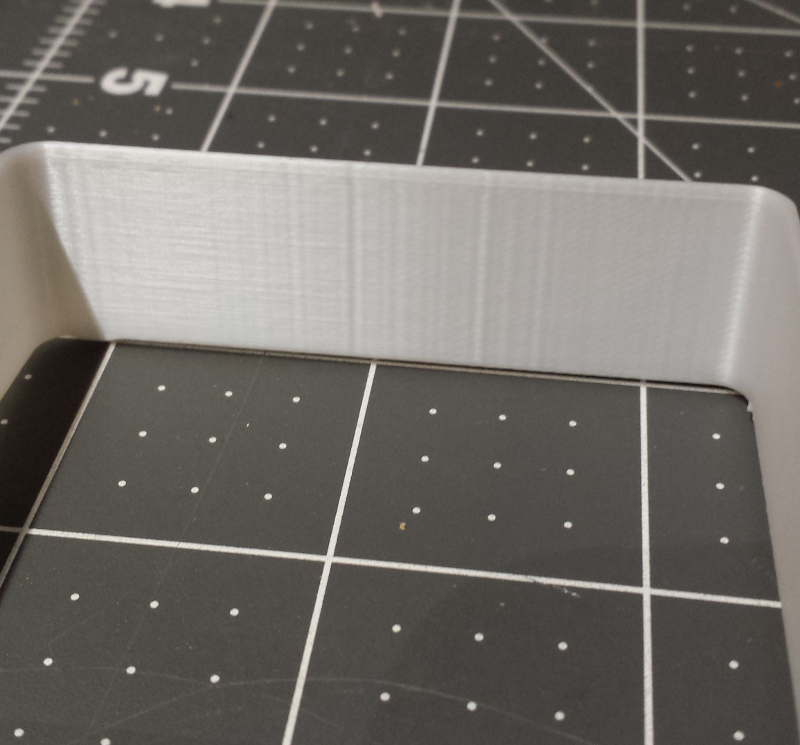
Wood PLA
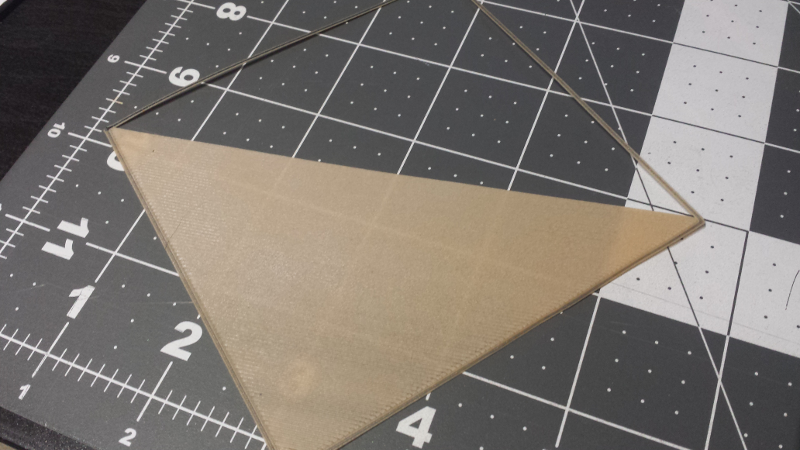
It was time to try a new kind of filament: “Wood” PLA, that supposedly gives a wood-like look to the finished piece. I first started printing a single layer square, to check that everything was all right with this new filament, and it was, I got a very nice/clean first layer so I stopped the test halfway through:
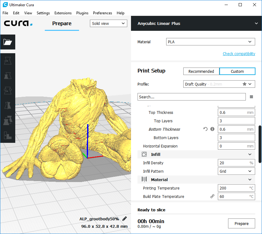
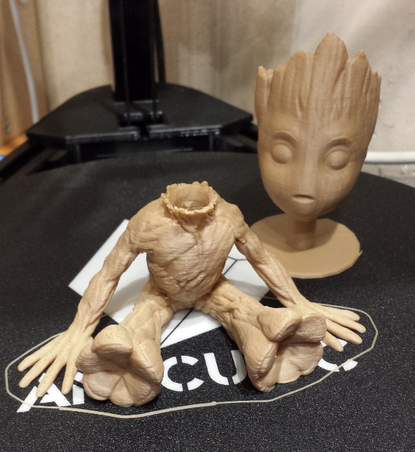
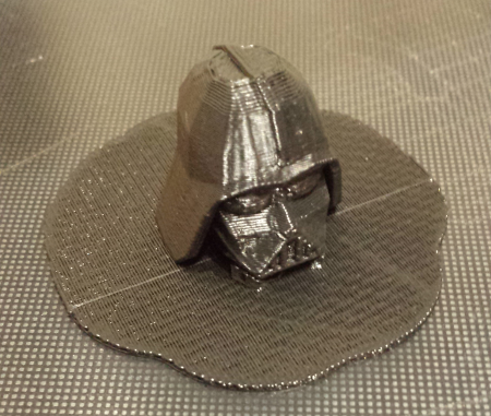
I proceeded to download a baby Groot model, it must have been printed a gazillion times around the globe by now, but it looks so cute and goes a long way in terms of the Woman-acceptance-factor for this new 3D printer.
The original model is quite big, I scaled it down to 65% in Cura.
Settings:
- layer height 0.2mm
- shell thickness 0.8mm
- infill 20%
- speed 40mm/s
- cooling enabled
- built plate adhesion: Brim
Here is a short video in the middle of printing:
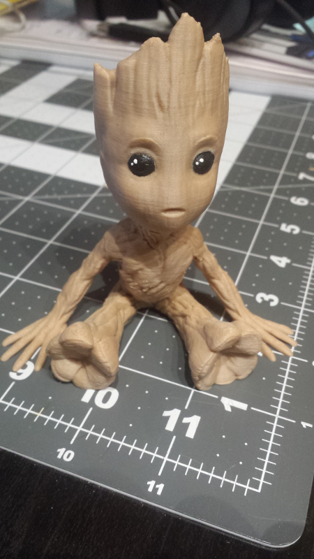
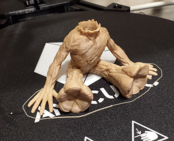
I was quite pleased with the resulting parts:
then I just painted its eyes, and ended up with this:
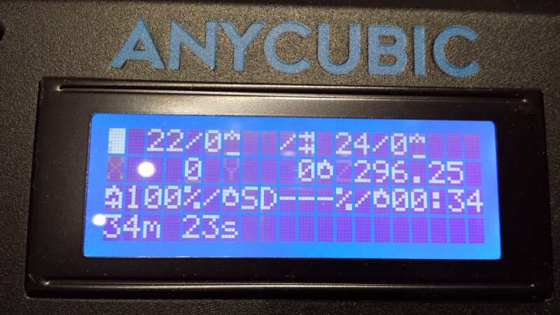
For some reason, I got this weird display bug sometime after the print was done. No visible consequence, the display went back to looking ok after reselecting another menu, so I will have to monitor if this happens again:
Bed adhesion options
There are various options in Cura regarding the build plate adhesion, I captured a few notes on each of them below:
Skirt
With this option, the printer begins the job by printing a single thin trail of filament around where the final part will be: as the filament may take a few centimeters to being to exit the nozzle properly and stick to the bed, this allows that any defect in the filament deposition happens on this useless skirt, not on the first actual layer of the printed object.
Brim
A Brim is kind of an extension of the skirt concept : a full single layer of filament will be deposited all around the object first layer, which has the same advantage as a skirt (getting a nice/smooth filament flow by the time the actual part printing starts) but adds the advantage to stick/stabilize the outer edges of the first object layer.
Raft
With this option, the printer begins the job by printing a base, slightly larger than the part to be printed, and onto which the first actual layer of the object will be laid. Useful to optimize bed adhesion (e.g. with ABS) and provide a good foundation for the object. This is like a multi-layer Brim, if you will. It does take a longer time to build.
Infill
The Infill parameter is quite straightforward to understand, it defines how much hollowness the slicer keeps inside the outline of the object on each slide. Here’s what a 10% Infill looks like:
Initial calibration tests
As first sanity check of the accuracy/calibration of the machine, I printed this part:
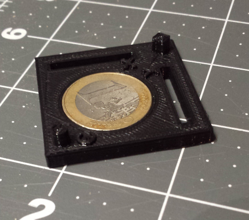
In theory, it has the following features:
- External dimensions XY 40mm => I measured 40.25mm along X, and 40.32mm along Y
- Internal cylinder hole to exactly fit 1€ coin 23.25mm => I was able to fit 1 euro coin in the hole, though with a tiny bit of resistance
- Small cylinder diameter 4mm => pretty much spot on
- Small cube side 4mm => I got 4.15mm and 4.25mm
- Diagonal dimension from cilinder wall to cube wall 40mm => I got 40.35mm
- Small dimensions from XY slots to outer wall 4mm => I got 4.21mm on Y, 4.13mm on X
- Z dimension of main plate 4mm => I got 4.10mm
- Z dimension from bottom to top of cylinder or top of cube 8mm => I got 8.21mm
Through the LCD menus (Control, then Motion) I checked the current settings of steps/mm of each axis:
- X axis: 80 steps/mm
- Y axis: 80 steps/mm
- Z axis: 80 steps/mm
- E axis: 96 steps/mm
I tried adjusting these values (Control menu, Motion, then scroll down to find X/Y/Z/E steps/mm), printed the object again, and measured it. Unfortunately….the X/Y/Z/E steps/mm params were not properly stored to memory, so upon power cycle of the machine the values were lost somehow, which made the calibration pointless. This seems to be a limitation (bug?) of Anycubic’s Kossel firmware version (as of early 2018).
This issue initially led me to consider modifying the firmware myself, since source code is available: the AnyCubic site provides a source code file here that supposedly corresponds to the firmware installed on the machine. I archived my own backup copy here, because who knows how long the company will be around. The firmware is derived from Marlin, which is readily available to download too, but requires customization to work with the Kossel.
I did not bother diving into the firmware until 6 months later, when I was nudged in the comments section of this page (thank you John Borg!) towards trying the Marlin 1.1.9 firmware, with Kossel modifications. But before anything, I needed to make sure I could come back to the original state of the machine, just in case.
Firmware backup & restore
Before starting the roll a new customized version of the firmware, I figured it would be mandatory to first make a backup of the binary firmware installed on the machine. Since the Kossel controller is designed around an ATMega2560 microcontroller, the usual Arduino tools apply, and one can use the avrdude command line tool to make a copy of the firmware stored in the machine Flash memory:
etabli@bids-etabli:~/arduino-1.8.1/hardware/tools/avr/bin$ ./avrdude -C ../etc/avrdude.conf -p m2560 -c stk500v2 -P /dev/ttyUSB0 -b 115200 -U flash:r:flash_backup_file.hex:i

avrdude: AVR device initialized and ready to accept instructions

Reading | ................................................... | 100% 0.01s

avrdude: Device signature = 0x1e9801 (probably m2560)
avrdude: reading flash memory:

Reading | ................................................... | 100% 27.66s

avrdude: writing output file "flash_backup_file.hex"

avrdude: safemode: Fuses OK (E:FD, H:D8, L:FF)

avrdude done.  Thank you.
This reads the Flash content over the USB link, and stores the retrieved firmware in a file using Intel HEX format. Similarly, the following command does the same operation but stores the firmware in RAW format:
./avrdude -C ../etc/avrdude.conf -p m2560 -c stk500v2 -P /dev/ttyUSB0 -b 115200 -U flash:r:flash_backup_file.raw:r
It is also important to backup the Arduino’s eeprom content, here are the corresponding commands for dumping the eeprom in Hex as well as Raw format:
./avrdude -C ../etc/avrdude.conf -p m2560 -c stk500v2 -P /dev/ttyUSB0 -b 115200 -U eeprom:r:eeprom_backup_file.hex:i
./avrdude -C ../etc/avrdude.conf -p m2560 -c stk500v2 -P /dev/ttyUSB0 -b 115200 -U eeprom:r:eeprom_backup_file.raw:r
Writing/restoring the flash/eeprom files uses almost the same commands but just using -U flash:w:flash_backup_file.bin and -U eeprom:w:eeprom_backup_file.bin
Migrating to Marlin 1.1.9 firmware
The vanilla version of Marlin 1.1.9 can be downloaded here.
Customizing Marlin to work for a specific printer boils down to updating two files:
- Configuration.h
- Configuration_adv.h
I started from the link John recommended, which pointed to files and video from this Da Hai Zhu guy, that I remember from earlier Kossel video browsing as being the best I could find at the time. I just had to do a few tweaks, since DaHai’s configuration is for the pulley version of the Kossel, while I have the linear plus version. Also, I compared each modified parameter to their original value in Anycubic’s linear plus firmware source code, and found a few discrepancies with Dahai’s values, so I chose to stick to Anycubic values for those.
Anyhow, I archived my customized version of Marlin 1.1.9 here.
The rest went smoothly:
- Launch Arduino IDE
- Open the file
Marlin.ino(which loads all other required files in the IDE) - Compile it
- Connect the Kossel to the PC via a USB cable
- Setup the Arduino IDE:
- Board: Arduino/Genuino Mega or Mega 2560
- Processor: ATMega2560 (Mega2560)
- then click
Uploadand….hold your breath. The upload took what felt like forever, in reality about 30 seconds, but I still sighed in relief upon seeing the completion message.
The updated firmware’s splashscreen showed up, all good.
NOTE : In this version of FW, baudrate is set to 250000 instead of the default 115200.
Re-calibrating with Marlin 1.1.9
All steps are very well explained in DaHai’s video, I capture them here for my own convenience:
- Install/connect the leveling probe (I have version 2)
- Launch
Prepare/Delta Calibration/AutoCalibration- this is fairly long as it will go down and probe multiple points, 7 times in a row.
- Launch
Prepare/Delta Calibration/Set Delta height- the head will come down and probe the height once
- Do
Prepare/Delta Calibration/Store settings- the machine will beep once to acknowledge
- REMOVE the probe
- Change
Prepare/Move Axis/Soft EndstopstoOff- note: the
Move Axismenu is not available until at least one homing has not been performed.
- note: the
- Now, using the
Move Z-axismenu, move Z down, first in large steps (10mm) to ~10mm height, then in smaller 1mm steps to ~1mm height - At this point, slide a piece of paper under the nozzle, switch to the smallest steps of 0.1mm, and bring the nozzle down by 0.1mm increments UNTIL the paper cannot be moved freely underneath. When this happens, raise Z by 0.1mm
- Make a note of the Z offset. If e.g. the paper can still be moved at Z=000.5mm, but cannot be moved at Z=000.4mm, then note an average Z offset of 000.45mm for the next steps.
- Note: the offset may be positive or negative.
- Go to
Prepare/Delta Calibration/Delta Settings, and adjust theHeightsetting by SUBTRACTING the Z offset you noted.- Note: the subtraction can end up being an addition if the captured Z-offset is negative
- Do
Prepare/Auto Home - Go to
Control/Motionand adjust theProbe Z-offsetby SUBTRACTING the Z offset you noted, as already done for theHeight. - Do
Control/Store settings - Do
Prepare/Auto Home - Now use the
Prepare/Move Axis/Move Z-axisagain to manually check whether the new settings are just right: lower the nozzle cautiously, using finer increments as you get closer to the bed surface, slide a piece of paper under the nozzle, and check that now the nozzle should come in contact with the paper at Z=000.0 (+/- 0.1mm).- If this is the case, all good. Else, adjust the two params (
HeightandProbe Z-offset) by the remaining offset, as explained above, and re-test.
- If this is the case, all good. Else, adjust the two params (
- Raise the nozzle and REATTACH the probe
- Do
Prepare/Level Bed - Do
Control/Store settings - Do
Prepare/Auto Home - REMOVE the probe
Once this is all done, you should have a nicely calibrated machine ready to print with a great-looking first layer. BUT, better safe than sorry, after this whole procedure, I suggest you triple-check that Z=0 really corresponds to the bed surface on the newly recalibrated machine. Just move the Z-axis manually (as described in the procedure) and check with a piece of paper that contact happens very close to Z=0.000. If contact happens for a small positive Z (say Z=0.5), restart/redo the calibration until it’s ok, otherwise the first job you launch will ruin your bed when the nozzle comes scratching it. Do not ask how I know…
Lithophane…and ringing
Lithophane is the concept of showing a image by shining light through an object of varying thickness. I gave it a try, using this site that does all the job of mapping any image onto a 3D shape, and producing an STL file accordingly. I used these settings for the test:
- 100mm height
- thickness 3mm
- border 0mm
- thinnest layer 0.8mm
- 4 vectors per pixel
and imported this image, which I chose to wrap onto a cylinder section:

The Cura settings for printing the STL were:
- layer height 0.2mm
- wall thickness 0.8mm
- infill 70%
- Brim
I got the semi-interesting result below, which I stopped halfway through:
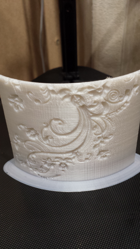
The pattern looked ok, and did look good with a backlighting, but these vertical lines kind of ruined the surface, so I decided to investigate a little bit.
I printed a simple cube, and sure enough got the same visible defect on the walls:
typical reasons for ringing:
- printing too fast
- firmware acceleration setting too aggressive
- mechanical issue
I first tried to add these rod dampeners, assuming the ringing was due to subtle vibration in the rods, but it changed nothing.
Anyway, I could not find a definitive way to get rid of these vertical lines, and it seems like they might be in part to the limited 8-bit resolution of the controller board. Higher-end controller boards exist in 32-bit flavor, and seem to go a long way to have a more precise control of the extruder head trajectory, and therefore have nicer looking walls with much more subtle artefacts. I will consider upgrading to such a controller in the future, but for now this is not a big deal on most models, so I learned to live with it.
Vase mode
There is an interesting (experimental) mode in Cura, that allows to only print the outer profile of a model, as a single spiral line of filament. Obviously it only works for models that are have no geometry “inside”, hence the popular name of this mode: “Vase” mode since this is what it works best for, making nice looking vases…
The option is actually called Spiralize outer contour in Cura’s Special Modes settings:
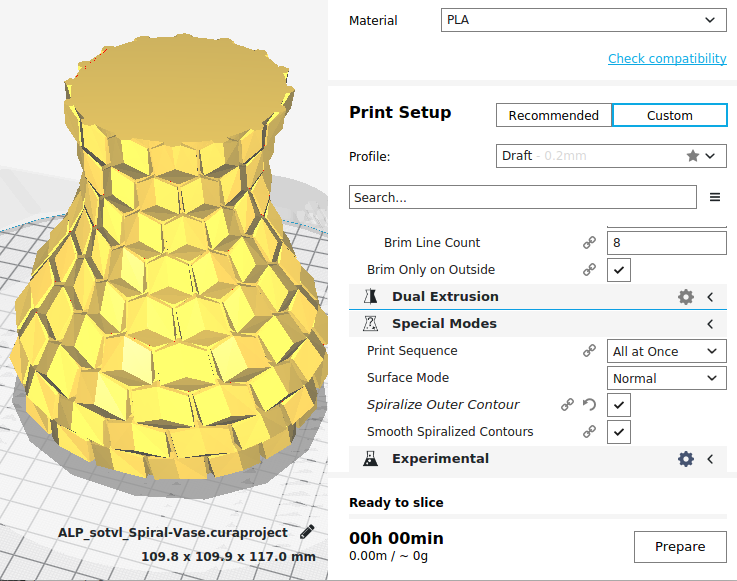
And here are a few results:
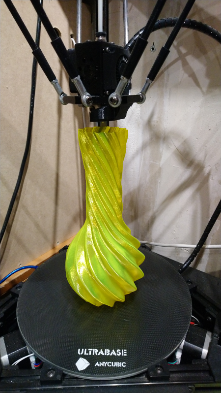
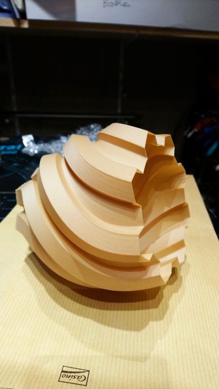
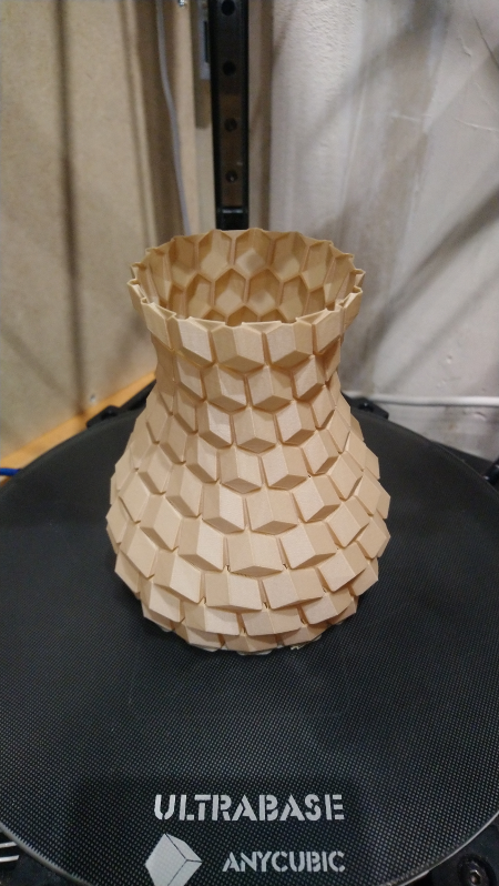
The regularity of the printed surface is SO much better than when using the regular printing mode.
Nozzle trouble
After a few weeks of use, I started getting intermittent “clonk” sounds, and noticed the extruder wheel was jerking back slightly each time. The problem came and went, from one print to the other. For some reason I convinced myself that the extruder was trying to push the filament too much, i.e. that the extrusion rate was too high. After a lot of head scratching and tests, it dawned on me that maybe the nozzle itself was the problem. On a hunch, I swapped the nozzle for a new one, and sure enough, immediately all the next prints were normal, no more clonking sound. This was my first-hand experience of a coggled nozzle, and a facepalm moment too for having lost so much time investigating elsewhere.
I did not bother unclogging the original nozzle, which I had abused over time anyway, and considering it’s not very expensive to replace anyway.
Upgrades
Bed
After a while I upgraded the bed for the coated glass one that Anycubic makes (ordered for about 30 euros from Banggood):
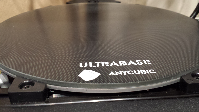
While not strictly necessary, it is quite pleasant to use compared to the stock bed cover. After objects cool down, it takes very little force to pull them from the base, so basically the scraper becomes useless.
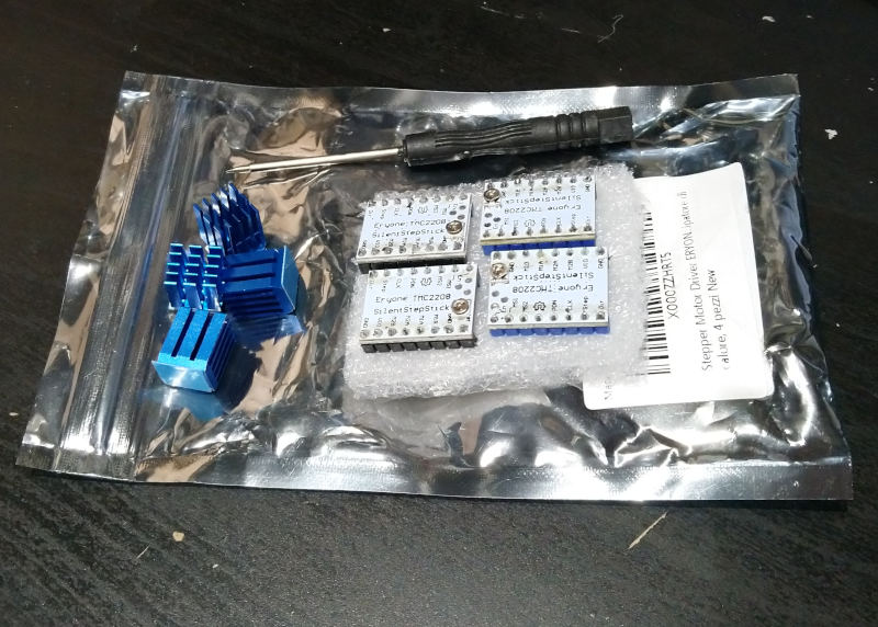
Silent stepper drivers
By far the most interesting upgrade I did is changing the original A4988 stepper drivers, for TMC2208 silent drivers (TMC2130 would have been a good choice too). Luckily, the stepper drivers are not soldered directly onto the Trigorilla board, but can be unplugged and replaced at will. I bought a set of 4 TMC2208s for about 20$, they came with (mandatory) heatsinks and a small screwdriver to adjust voltage (more on this below) :
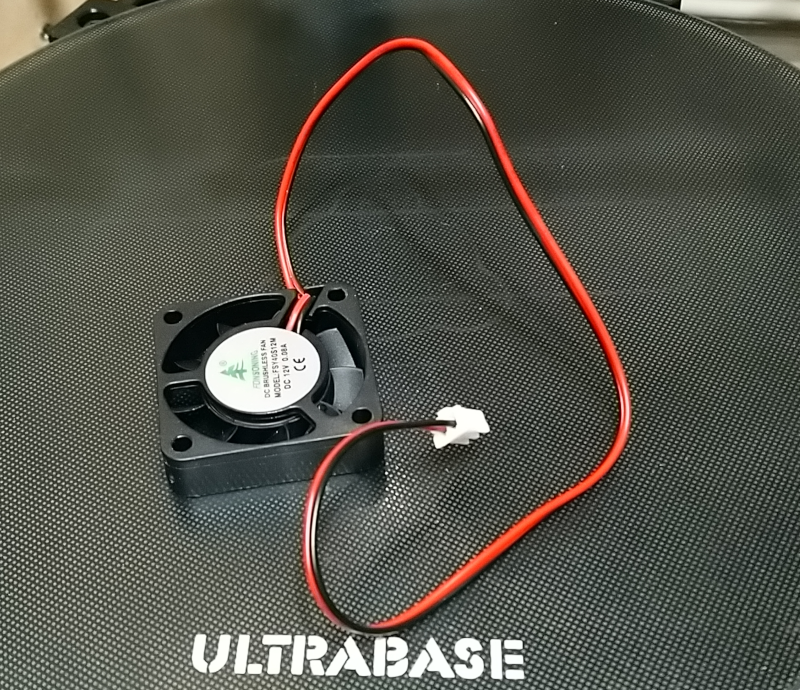
These TMC2208 modules tend to heat up during operation, so they require both the heatsink to be placed on the top of the PCB (the chip is soldered on the other side) AND to use a fan to have a constant air flow through the heatsinks. I chose to 3D print this fan duct, so I bought a small 40x40mm 12V fan :
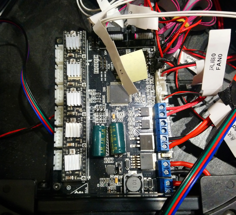
I unplugged the machine, and disconnected the stepper motors cables (X/Y/Z/E0), and took a picture of the old A4988 drivers just in case:
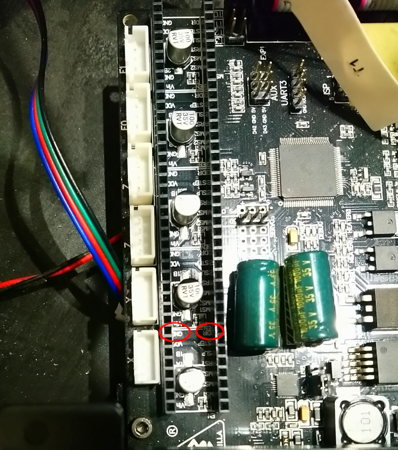
and then I removed them, and located the GND and DIR signals on the PCB: it is CRITICAL to plug the new TMC2208 with the right orientation, and matching GND/DIR on the PCB and GND/DIR on the modules is the only sure way to do this:
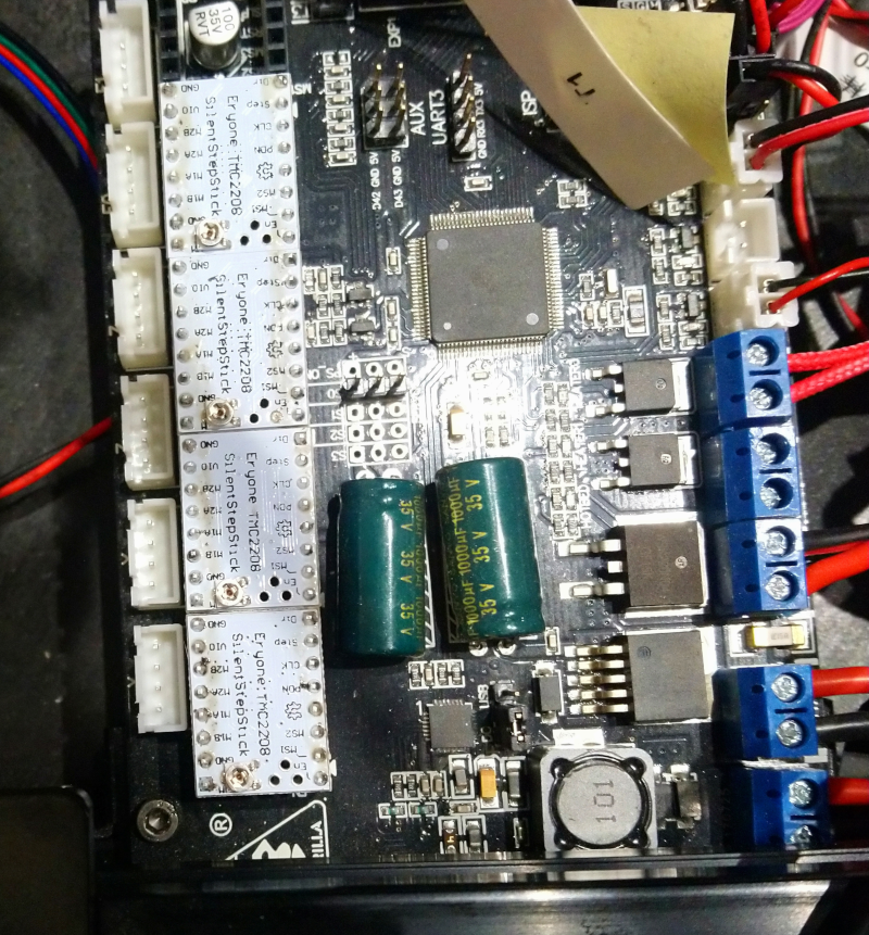
With the four new drivers in place, notice how the small voltage potentiometer is NOT on the same side as it was with the A4988, so again locating GND/DIR is the only sure way to plug them correctly:
Then I installed the heatsinks, making sure they were oriented correctly for the airflow of the fan duct. Finally, I adjusted the reference voltage on each driver, which required to power on the machine:
- I used a voltmeter to measure voltage between a GND point (I chose the connector circled in the bottom right of the picture below), and the tiny potentiometer of each driver (also circled below)
- by default they had various values around 1V. I followed Da Hai’s advice and went for 0.9V on the X/Y/Z drivers, and 1.1V on the E0 (extruder) driver. The adjustment is made by turning (VERY carefully) the potentiometer, with the tiny screwdriver, while making sure to not touch anything else.

Then I installed the fan duct (it just slides from the side and clips to the PCB, very smart design), and plugged the fan in FAN1 connector:
The final step was to make a few changes in the Marlin firmware, in Configuration.hfile:
First, the new fan to cool the 2208s is plugged on the available “FAN1” connector on the TriGorilla board but by default in the 1.1.9 firmware this output is not activated. I uncommented #define USE_CONTROLLER_FAN
and set #define CONTROLLER_FAN_PIN 7 (FAN1 happens to be pin7 on the board, while FAN0 is 9 and FAN2 is 44). With this modification, Marlin will turn on FAN1 whenever the stepper drivers are activated.
Then, I had to toggle the value of INVERT_X_DIR, INVERT_Y_DIR, INVERT_Z_DIR, and INVERT_E0_DIR, to ensure proper direction of movement (don’t ask, the TCM2208s just drive the motors in a different direction than the A4988 by default)
Finally, I changed the X_DRIVER_TYPE, Y_DRIVER_TYPE, Z_DRIVER_TYPE, and E0_DRIVER_TYPE from A4988 to TMC2208_STANDALONE
I rebuilt the firmware in the Arduino IDE, powered the machine, and flashed the modified FW to the board, and voila : the motors are now silent, just the fan noise remains (especially considering the added fan, so you may want to pick a silent one: I later replaced the basic 40mm fan mentioned above by a silent one and it was worth it).
Homing switches glitch filter
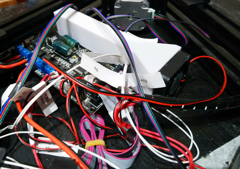
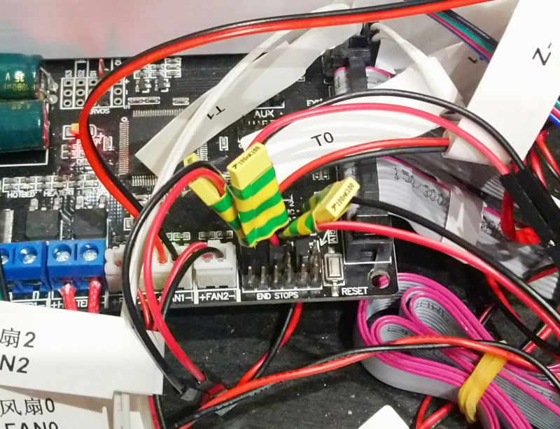
For a long while, I had an intermittent issue when SOMETIMES, during the final homing at the end of a print, the printer would raise one axis only instead of raising each axis, and this would end up in crashing into the tower. Very unpleasant sound, and not very good for the machine. After a little googling, it seems that the most likely cause for this behavior is an electrical glitch happening during homing, on the stop switches signals: the controller will interpret the glitch as a detection that the switch has been triggered, and therefore will top motion on that axis since it considers it is homed. Anyhow, I tried SW cures in the firmware (SW debouncing of the signal) but it did not work, and I finally resorted to adding a 100nF capacitor in parallel on each of the three switches. The capacitors need to be placed as close as possible to the board, so I hacked three little extension cables with the 100nF cap soldered on them:
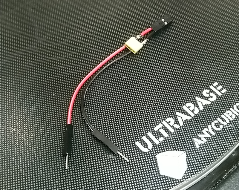
and inserted these extensions between the switches headers on the board, and the switches wires:
Ever since I have not had the homing issue again, fingers crossed.
Note: at some point I had a ‘Probing failed’ error during the calibration procedure: this was just because there is a hardcoded limit in the firmware to how “far” the Z probing is allowed to go until a contact is detected, and for certain combinations of steps/mm and Z height, the probe may reach this limit before reaching the bed. I modified the Z_PROBE_LOW_POINT parameter in configuration.h from -2 to -20 (millimeters) and got rid of that annoying issue.
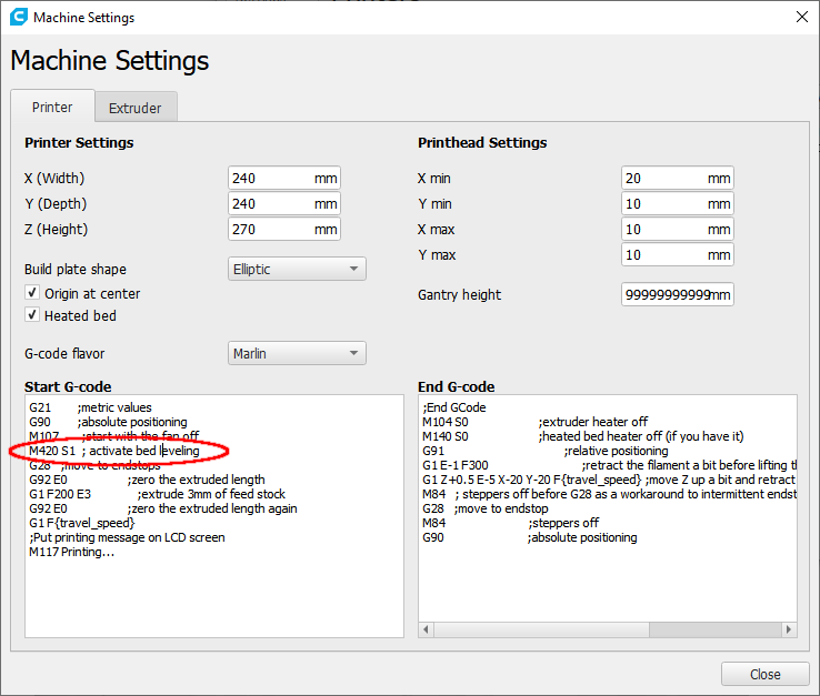
Also, I realized that at power-up, bed leveling in not active by default in Marlin, and it’s very easy to forget about activating it. To address this I added the bed leveling acivation G-code command (M420 S1) in the header of the G-code post-processor in Cura:
Misc
- I archived a copy of the Kossel user manuel here in case I lose the paper one.
- Here’s a view of the stock Trigorilla controller board:
Conclusion
I honestly would not have thought that I could get a decent 3D printer for 250 euros. It may not be perfect, but after a few months of using it I can confirm it suits my needs perfectly, i.e. it just works when I need it, performs quite well, is a lot of fun to use and watch printing stuff. After 6 months or so I migrated to Marlin v1.1.9 with Kossel-specific customizations, and I feel more in control now that I know for sure what code & settings are actually running the machine, and knowing that I have the ability to change them if needed.