
A journey with the Shapeoko3 CNC
Overview
I had been thinking about getting a CNC machine for years, for all these project moments when I told myself “wouldn’t it be nice if I had a way to cut this enclosure/part in a cleaner/faster way?”. For a long time I told myself the investment was not worth it in my case, but I eventually decided to go for it anyway, more for the sake of getting a little CNC experience than for a real specific need.
A quick search left me with three main options:
- building one from scratch: probably the most interesting in terms of learning experience, but beyond the time it would take, I felt I would end-up with a sub-par machine and would get frustrated in the end.
- buying a cheapo kit from Asia: definitely the cheapest option, but even though I buy dirt cheap electronic components there all the time, I am not willing to spend several hundred dollars and not be quite sure of what result I will get in the end.
- buying a high-quality kit while still staying in the hobbyist budget range: Google soon narrowed it down to these two options, which have common DNA:
- X-Carve from Inventables
- Shapeoko from Carbide3D
I finally decided on the Shapeoko3 (the standard size version) after a bit more browsing on the interwebs. 1100$ + shipping + import taxes is a lot of money for a casual CNC experience, but it is also very good value for money considering the quality and versatility of what you get, and I could not find any decent equivalent product locally in Europe.
- Overview
- Safety disclaimer
- Synoptic
- HW build and SW setup
- Software
- Initial tests
- Adding the Router
- Cutters & accessories
- Toolpaths
- Feeds and Speeds (theory)
- Initial milling tests
- Enclosure
- Chips/dust collection
- Making a wasteboard
- Surfacing
- Workholding
- V-carving a small plaque
- Feeds and Speeds (Practice)
- Plunge rate and Plunge depth
- Shapeoko calibration / tuning
- Feeds & Speeds calibration
- Router RPM calibration
- Abusing Carbide Create
- Maintenance
- Misc notes
- Lessons learned (so far)
Safety disclaimer
a CNC like the Shapeoko can cut though plastic, wood, and aluminum, includes a router that spins a cutting tool at several tens of thousand RPMs, and moves in three dimensions under the control of software that may or may not have bugs, executing a program that YOU designed : it is in short a beast that is only partially tamed, so as the manual says, “Use common sense” if you don’t want to loose an eye or finger.
Safety goggles are your friend:
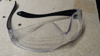
Also, make sure you have a kill switch / emergency stop button at hand, that removes all power from the machine.
Synoptic
A simplified Shapeoko setup is represented below (front view, i.e. X/Z view, Y is depth):
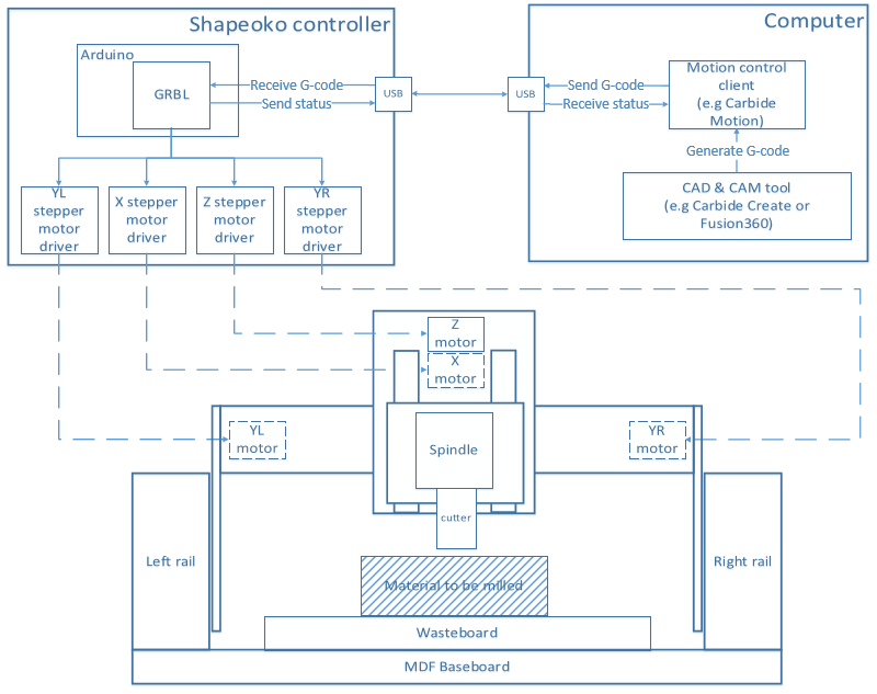
- an MDF baseboard supports the front and rear steel plates holding the left and right rails in place
- a gantry moves along the Y axis onto the left and right rails, controlled by two NEMA23 stepper motors (YL and YR)
- the gantry supports the X/Z plate
- the X stepper motor moves this X/Z plate in the X direction on the gantry rail
- the Z stepper motor moves the Z plate in the Z direction on the X/Z plate rails
- the Z plate supports the spindle
- the stock material to be machined is (usually) attached on top of the wasteboard (i.e. sacrificial board that can get changed regularly)
- the motors move under commands from the shapeoko controller
- which is basically an arduino controlling four motor drivers and a few discrete signals
- the controller communicates with a host PC over USB to receive milling programs (in G-code format), and uses GRBL to interpret them into actions on the motors, and send back real time statuses.
- the controller has its own power supply (not shown), the router is powered separately from mains.
HW build and SW setup
Unpacking
After crossing the atlantic ocean (shipping: 233$, ouch), and clearing French Customs (an additional 180 euros in import taxes, ouch), the bulky package arrived on my front door:
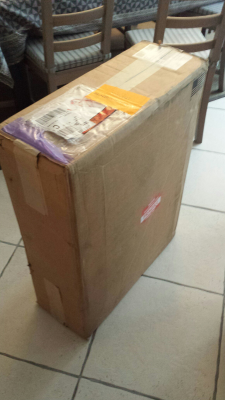
A nice thing is that this is only the outer packaging, that took the small hits during transport, while the actual shapeoko cardboard package is inside:
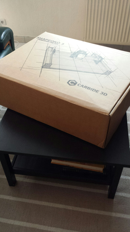
And then all pre-assembled pieces come in their own package too:
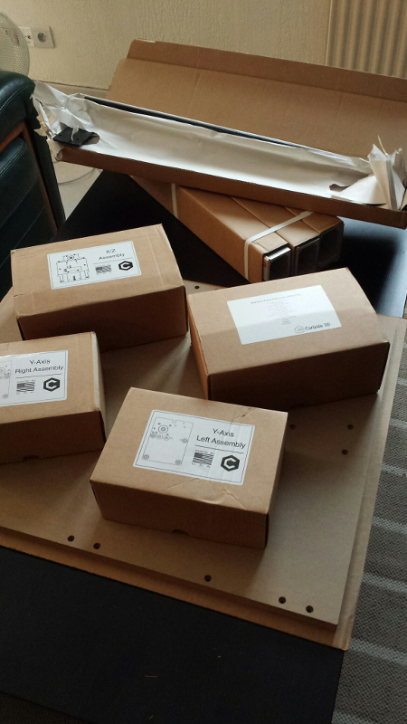
Overall, while I was slightly worried about the long distance shipping, everything came out of the box in perfect condition. I must also say I got a very good feeling about the quality of all parts: it all looked and felt like quality parts. As I live in the Old World I did not really care that much about “made in the USA” before the purchase, but it clearly shows.
Assembly
I then assembled the machine, strictly following the online instructions, overall everything went smoothly. I was very glad the X/Y/Z assemblies come pre-assembled, less opportunities for mistakes, and it is still fun to assemble all the rest.
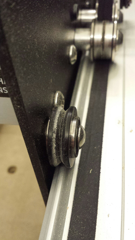
Notes from my experience:
- the part about rotating the excentric nuts in the correct position BEFORE sliding sub-assemblies onto their associated rails is quite important. So take time to check this, rotating the excentric nut (clockwise only), ensuring that the V-Wheels are positioned so that the sub-assembly can be slided onto its rail with zero friction (it should even be loose), and then once in place on the rail rotate the excentric nut in small increments, iterating until the V-wheel touches the rail and there is no play, but NOT MORE. The assembly should still slide with no effort on the rail.
- I was cautious to not over-tension the belts, especially since there is an explicit note in the instructions for the Z-axis belt, that excessive tension could damage the Z stepper motor shaft. I erred on the side of too much caution though, the Z movement felt OK when moved by hand, but during the very first controlled motion of the Z-axis, the belt slipped (and the associated noise is quite scary). Re-tensioning the Z-belt being a little less convervative fixed the problem.
- Squaring the machine is obviously a critical step, and this is where I struggled:
- I followed the squaring procedure religiously… but ended up with a quite significant gap (~2mm) between one of the gantry plates, and the rear plate.
- this meant that my gantry was not perfectly perpendicular to the Y axis.
- I loosened all screws and re-started the squaring procedure from the top…and ended up with the exact same result.
- I precisely measured the length of both Y rails, as well as the distance between them both at the front and at the back of the machine, and saw that it was very precisely identical: so the problem did not come from the base frame or Y rails, but from the gantry.
- I loosened all gantry plate screws completely, identified which way the gantry was “bent”, used aluminum foil folded over 4 times to make a shim, inserted it at the right place between the gantry rail and the gantry plate, did the same on the other side (with the shim inserted on the opposite side of the gantry), and re-fastened the screws: SUCCESS ! I now had near-perfect contact between gantry plates and front/rear plates, on both sides.
- When attaching the cables to the controller, the two connectors for the two Y axis are labelled
Y1andY2:Y1corresponds to the LEFT stepper motor,Y2to the RIGHT stepper motor (looking at the shapeoko from the front) - I installed the Shapeoko on an old Ikea kitchen table I had in the garage, that happened to be exactly the right size. But I noted that the table was not stiff enough, and wiggled a bit too much, so I bolted it to the wall: problem solved.
- I initially placed a 1 cm rubber mat under the shapeoko (the black kind that usually goes under washing machines to minimize noise/absorb vibration), but this turned to be counterproductive: the shapeoko oscillated slightly during rapid gantry movements, due to the elasticity of the mat. So I removed the mat and let the shapeoko rest directly on the table, adjusted the four feet, and it was stable enough this way.
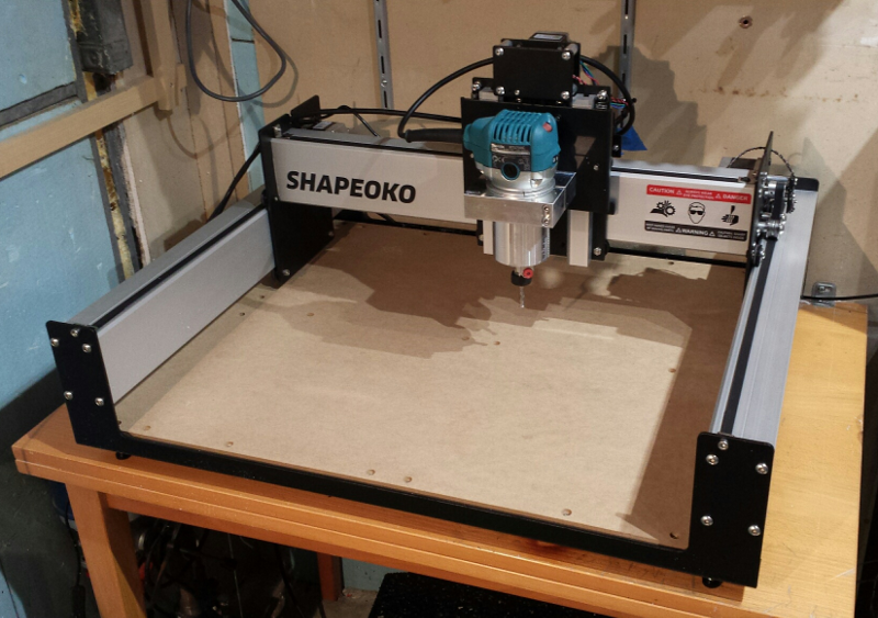
Front view of the assembled machine:
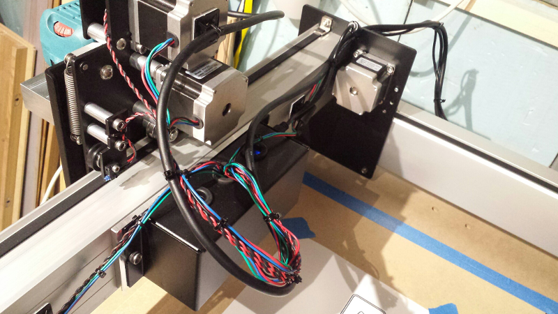
Motors, homeswitches and router power cables are routed and strapped together as recommanded in the last page of the shapeoko3 manual:
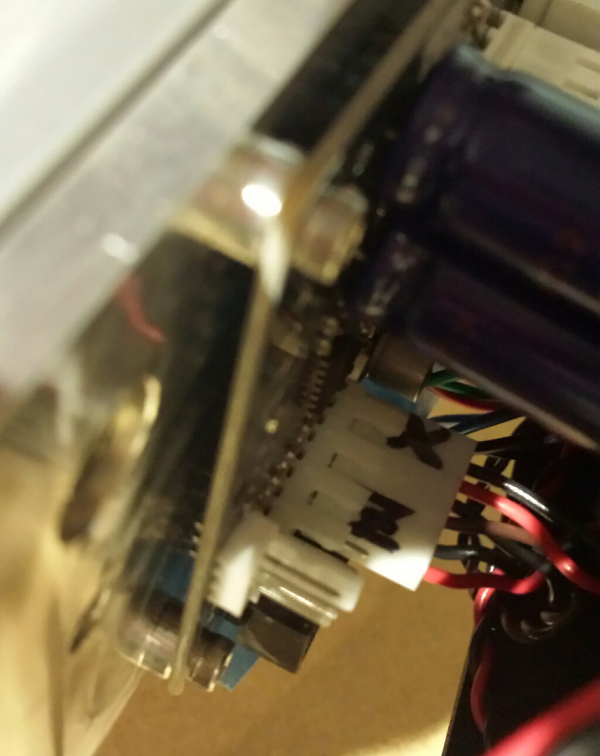
A view of the motor connectors cabling on the controller:
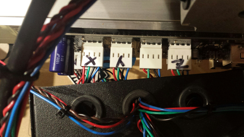
A view of the homing switches connectors on the controller (the middle unmarked one is Y):
Software
The CNC workflow is twofold:
- Create a model of the milling operations to be performed to get the desired resulting object, and generate corresponding G-code
- Send the generated G-code to the CNC machine, and let the controller interpret it to perform the appropriate actions.
There are many options for each part. For modelling & generating G-code,
- Carbide3D provides a SW called Carbide Create, originally limited to use with the Shapeoko or the Nomad (their other higher-end CNC product), but that can now used for pretty much any CNC as it generates standard G-code.
- the other popular option at the time of writing is
Fusion360from Autodesk, a full-fledged 3D modeller for makers that embeds a set of CAM features for creating toolpaths and generating G-code, and is free for hobbyists. - (many) other specialty CAM software exist, but most are commercial.
For sending G-code to the controller,
- Carbide3D provides a SW called Carbide Motion, a simple interface for Windows and Mac, for interacting with GRBL in the shapeoko controller, to jog the machine into position, load a G-code file, and execute it.
- MANY alternative GRBL clients exist, of all shapes and forms, like Universal G-Code Sender (UGS), so Linux users may look at that.
The Carbide SW toolsuite is an excellent way to start, it gets the job done and is very simple to learn. So I went this way, even though I felt that sooner or later I would outgrow it and I would have to learn Fusion360 for advanced projects.
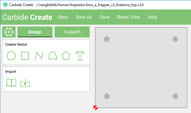
Installing and using Carbide Create
I installed the Windows version of Carbide Create, to experiment with a first design. While launching CC, I noticed that values in all fields showed up in red…not a good sign. Also, I could not input a dot in these fields, and I could input a comma but the number would then not be recognized properly. I emailed Carbide3D’s support, got an answer within 20 minutes (!) that CC was not yet properly internationalized, so it did not like my French Windows setup that uses commas in decimal numbers. The fix was just to change the decimal symbol from “,” to “.” in Windows settings:
From the Windows Control Panel, open Regional and Language Options, under the Format tab click Additional Settings and set Decimal Symbol from “,” to “.”
This problem being solved, I followed the excellent video tutorials available on Carbide3D’s site, and was able to create basic programs in no time. The last step is to generate the G-code program that will be sent to the machine.
Installing and using Carbide Motion SW
I installed the Windows version (a Mac version exists, no Linux version exists but alternate programs to do the same do exist) since I wanted to use Autodesk’s Fusion360 later anyway, and as of writing this there is no Linux version. CM is very a simple, clean, no-nonsense interface, does the job perfectly. After launching CM, the workflow is :
Connectto the machine- perform
Homing- this must first be enabled by sending the
$22=1command to the shapeoko using CM’sMDImenu. - Homing will move X/Y/Z axis to the back right corner, until they come in contact with homing switches, then move back by 5mm on each axis.
- this must first be enabled by sending the
Jogthe gantry manually to start position- X and Y can be moved fast initially, then reduce the step to precisely position them above the starting point.
- Z needs to be moved slower towards the surface, with very small increments near the end (0.1mm or less), until the tip of the bit/mill/pen mounted on the spindle is just in contact with the surface to be machined. The usual way to achieve this is by sliding a piece of paper back and forth flat on the surface and just under the tip, and moving Z down by one increment, and repeat until you can feel the paper being scratched by the tip.
- CRITICAL: zero the positions (from the
Set Zeromenu =>Zero All)- you will only forget to do this once, because it will likely result in crashing the machine: since all executed G-code commands are relative to a predefined zero point, if you forget to (re)set the zero position, the old zero from the previous run will be used, it may be somewhere else completely, and there is a high change your toolpath executed from the wrong starting point will end-up in a collision somewhere. You have been warned !
- USEFUL: memorize the current position to come back to it later (from the
Set Zeromenu =>Clear All Offsets)) - load a G-code program
- run the program
- the first thing that will happen is usually that the spindle will back off the surface and wait, this is intended to let the user check/mount the proper endmill and start the router.
- also CRITICAL: keep you hand near the emergency button/kill switch during the execution, at least for the first time you run a new design:
- after all the machine obeys SW commands created by a human being, humans make mistakes all the time: you should ASSUME that your milling program is incorrect, at least the first time you run it.
- simulating/pre-visualizing the toolpath beforehand helps mitigating this risk, but you can never be 100% sure. Even if the toolpath is correct, mechanical problems may happen.
A glimpse at G-code
There is very seldom a need to look at the G-code itself, and even less times when modifying G-code manually is required, but just out of curiosity, here is what the first lines of the Hello World G-code program looks like:
T1M6  (=> Stop and request to change to tool #1)
G17  (=> select plane XY)
G21 (=> use millimeters as the unit)
G0Z20.000 (=> rapid move Z=20)
G0X0.000Y0.000S12000M3 (=> rapid mode X=0 Y=0, spindle speed 12000RPM, start spindle clockwise)
G0X41.332Y104.662Z6.000 (=> rapid move to X=41.332, Y=104,662, Z=6.000)
G1Z-0.254F1524.0 (=> linear move to Z=-0,254, Feedrate 1524mm/minute)
G1X40.860Y104.856F5080.0 (=> linear move to X=40,860, Y=104,856, feedrate 5080mm/minute)
X40.403Y105.064 (=> etc...)
X39.961Y105.286
X39.535Y105.521
X41.846Y111.888
X42.694Y111.444
X43.559Y111.050
(etc...)
Initial tests
Time for the first power-up: I hooked-up the USB cable to my desktop PC, launched Carbide Motion, tried to connect…and got a Cutter did not respond error. Major bummer. A few hours later after various tests (using a laptop, changing the USB cable, routing it away for other cables, changing the order I turned on the shapeoko versus plugging the USB cable), I unmounted the shroud placed over the controller, to check what was going on in there.
The POWER led was lit (good), and while trying to connect the RX led was flashing a few times (good), but the TX led stayed dark (BAD! no communication back to PC)
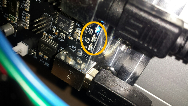
Then on a hunch I pushed the small RESET button:
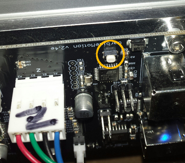
and immediately heard the stepper motors come to life/click in place, after which I was able to successfully connect from Carbide Motion.
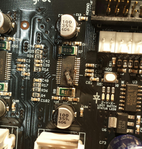
I contacted Carbide3D support, they immediately offered to ship a replacement controller, but were also interested in diagnosing the issue remotely if possible, since it is not always easy for them to reproduce customer problems once the faulty boards get back to them. Based on the symptoms I described, they analyzed possible causes, and a few emails later asked if I could try to remove resistor R50, that may have prevented the arduino reset to occur when connected over USB. I was in the mood for trying this fix, so I located the resistor:
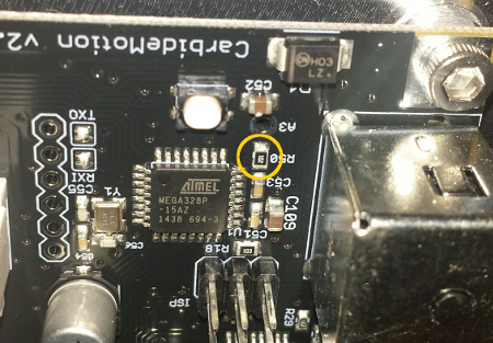
Unsoldering a tiny SMD resistor placed close to other components, and knowing I would have to wait for weeks to get a new board if I screwed up, was quite a stressful moment…but I managed to do it. Below is a souvenir picture to remember how tiny this thing is:
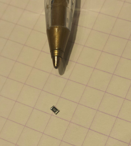
A few tests later I confirmed that removing R50 fixed the issue, my shapeoko now properly reset and clicked in place at power-up.
Power-on sequence
I stick to this sequence:
- starting with Shapeoko OFF, router OFF, USB cable connected to the PC
- launch Carbide Motion
- turn on Shapeoko
- click “Connect” in Carbide Motion
- click “Begin Homing”
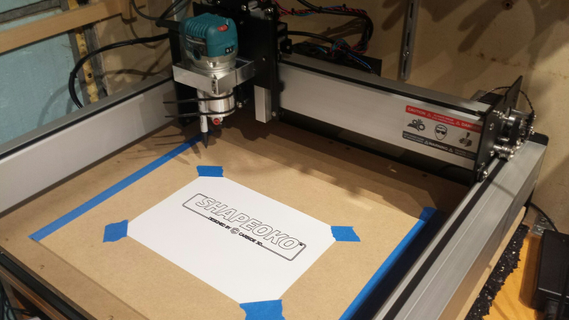
Hello Word example
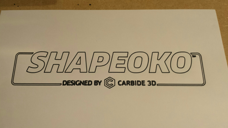
I proceeded to complete the traditional “Hello World” Shapeoko tutorial, which consists in attaching a sharpie marker to the spindle, and running a program that draws the Shapeoko logo.
So far, so good, the drawing seemed precise, nothing was obviously off. Close-up of the result:
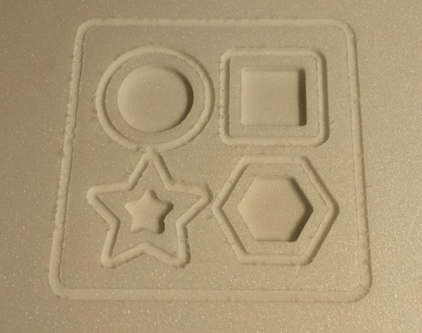
Basic geometry check
To check the squaring/alignment/calibration of the machine, I created a simple pattern of geometrical shapes of known dimensions.
I could not find any settings recommandation anywhere for using the shapeoko as a pen plotter, i.e. when the tool must stay on the surface. Carbide Create does not include a “Sharpie” tool in its list, which would not make a lot of sense anyway. So I had to guess, and cross my fingers:
- I set material thickness to 1mm (arbitrarily)
- After reading the G-code from the Hello World sample, I saw they were using a “cut depth” of 0.01 inches = 0.254mm. I thought 0.2mm was a bit too much when using a pen which point is not a soft as a Sharpie’s, so I finally used 0.1mm.
- I selected the tool that gave me the feedrate of 1524mm/minute, just like in the Hello World example
I then run the program, and then measured the results on paper:
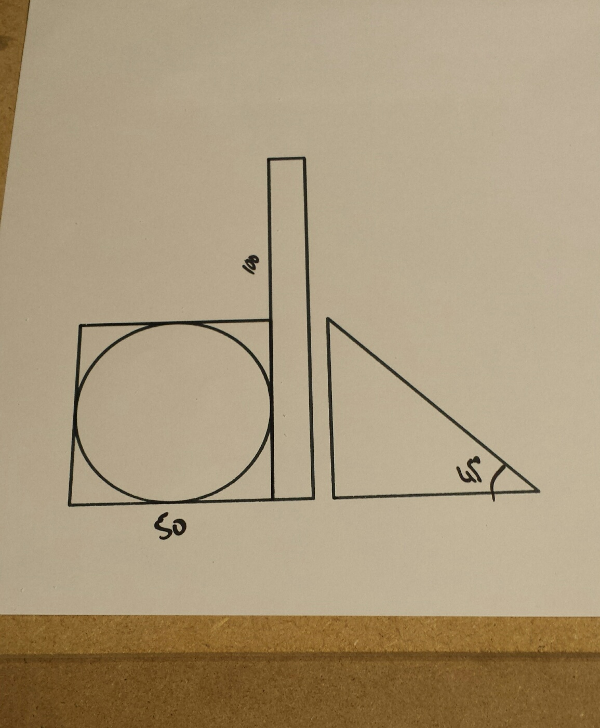
(values obviously written manually afterwards)
Using a tape and protractor I checked that dimensions were (visually) very close to the ones specified in the model: good enough for my needs at least so far. I am not a precision freak (yet), and there are ways to finetune the shapeoko to get high(er) precision, but I will address this later.
Adding the Router
The router can be purchased along with the shapeoko, but they only ship the 110V models, not compatible with European 220V mains, so I purchased the router separately. The two usual router choices for the Shapeoko are the DeWalt DWP611 or the Makita RT0701C (US versions), I went with the Makita option and ordered the European version (RT0700C) locally:
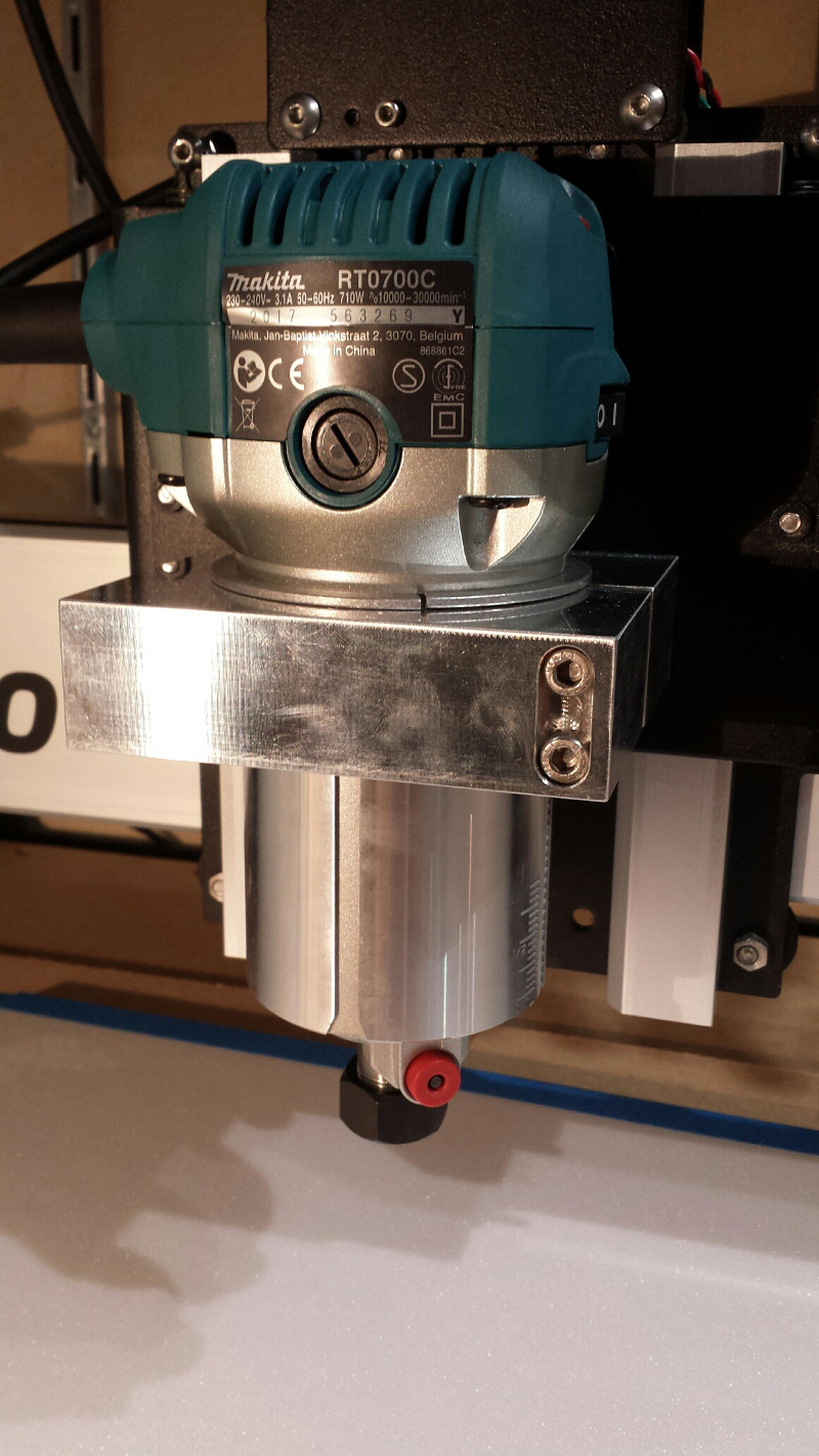
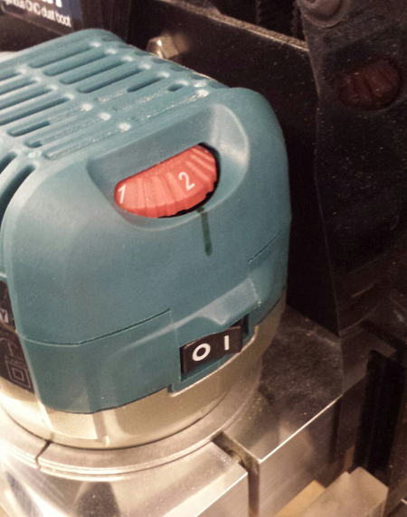
The dial on top of the makita (not visible on the picture) sets the rotation speed:
- Dial position 1 => 10,000 RPM
- Dial position 2 => 12,000 RPM
- Dial position 3 => 17,000 RPM
- Dial position 4 => 22,000 RPM
- Dial position 5 => 27,000 RPM
- Dial position 6 => 30,000 RPM
Cutters & accessories
Collets
the Collet is the part that holds the mill bit in the spindle. The RT0700C version of the Makita router comes with one 6mm and one 8mm collets :
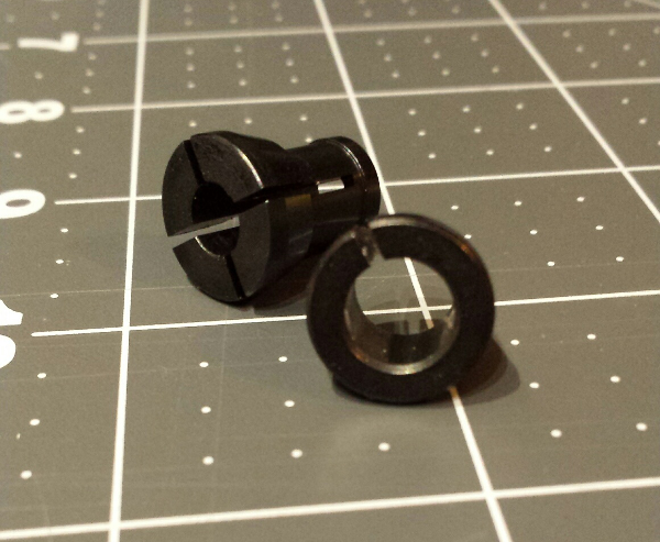
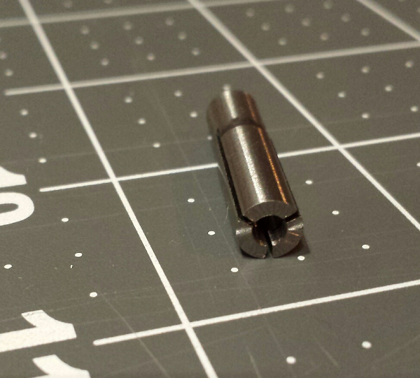
Since the rest of the world mostly uses 1/4” (6.35mm) and 1/8” (3.175mm) cutters, I purchased a 6mm to 3.175mm (1/8”) collet adapter:
and a 1/4” collet (Makita reference 763637-1)

End mills
I felt overwhelmed at first by the variety of bits and their characteristics, it’s a whole world in itself. I narrowed it down to a somewhat naive/beginner’s view:
- an endmill is caracterized by:
- its type:
- square: the most common type, a straight endmill with square end, used to machine flat pockets/recesses
- up spiral: the direction of the flute is such that it pulls chips away from the cutting surface, thus is quite efficient at removing chips, but could produce tear out on the material surface.
- down spiral: pushes chips downward when cutting, so not efficient to remove them from the cutting area, but can reduce tear out on the material, for a better finish.
- ballnose: it has a round tip, which helps getting a better finish on 3D-machined parts (i.e. produces less visible steps)
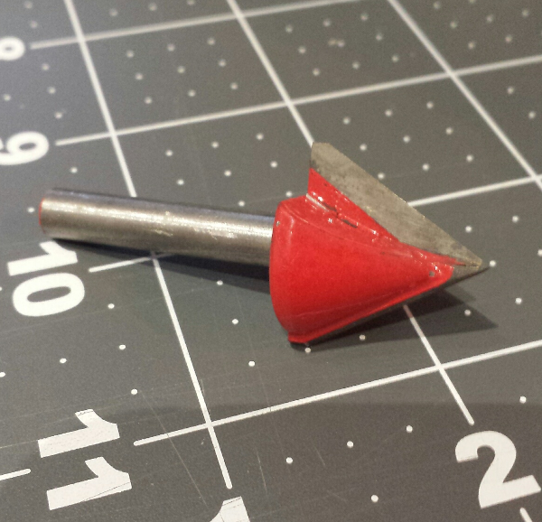
- V-bit of a given angle: specialized bit typically used for carving text.
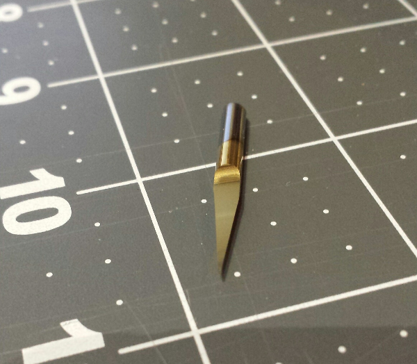
- other specialized types (engraving bit with a very pointy end, surfacing bit which is a square bit with a very large diameter)
- square: the most common type, a straight endmill with square end, used to machine flat pockets/recesses
- whether it is center cutting or not. Most are, it means it has the ability to plunge into the material (vertically), like a drill bit does.
- the diameter of its shank (the part that goes in the collet)
- the diameter of its cutting part
- the length of its cutting part, and its total length.
- the number of flutes = number of cutting teeth
- the material it is made of, and potentially the coating on the cutting part
- its type:
- in countries that use the imperial system the most common endmills are 1/4” (6.35mm) and 1/8” (3.175mm)
- in countries that use the metric system the most common endmills are 3.175mm, 4mm, 6mm and 8mm
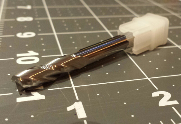
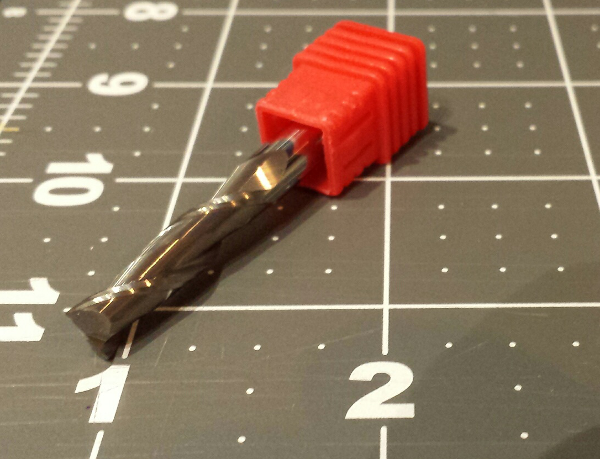
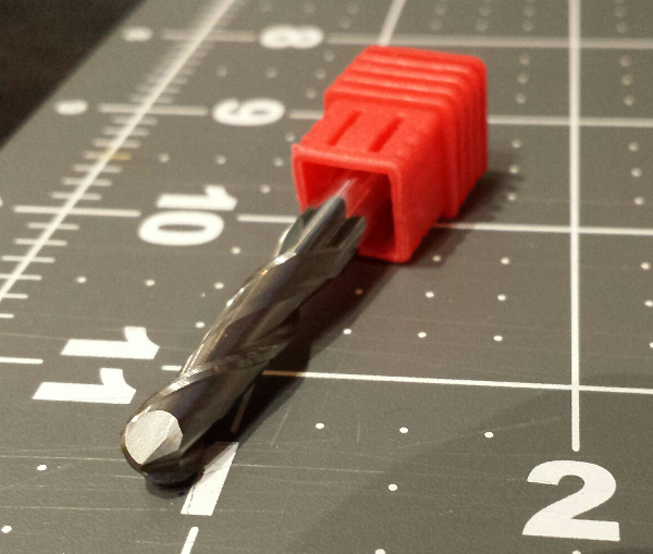
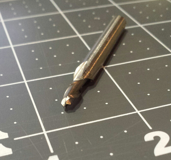
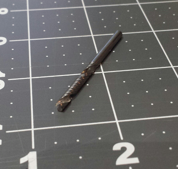
My starter set of mills is composed of:
-
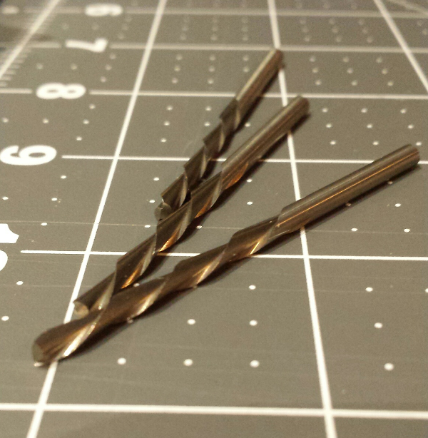
the 3-flute 1/4” (6.35mm) square endmill that ships with the Shapeoko3
-
a 2-flute square 6mm carbide endmill
-
a 2-flute ballnose 6mm carbide endmill
-
a 2-flute ballnose 2mm endmill with 6mm shank
-
a 1-flute square 3.175mm endmill
-
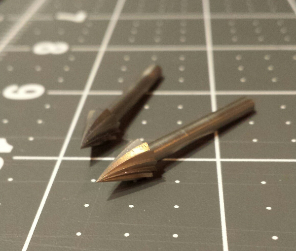
90° V-bit
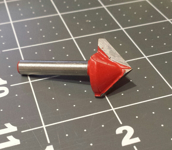
-
60° V-bit
-
a 0.1mm engraving bit
-
Some 1/8” (3.175mm) Dremel #561 endmills I had
-
Some 1/8” (3.175mm) Dremel #125 high speed cutters, that happen to be downcut (helpful sometimes)
-
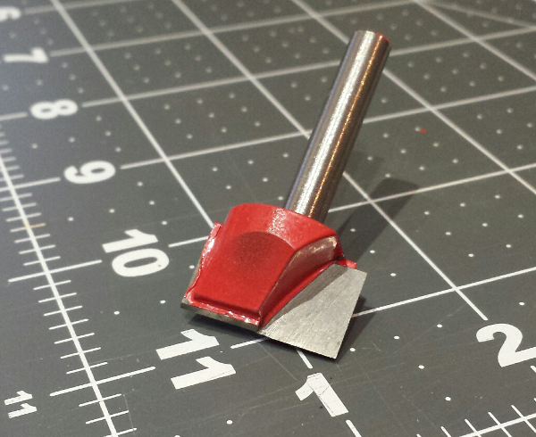
a surfacing bit
Toolpaths
Toolpaths types
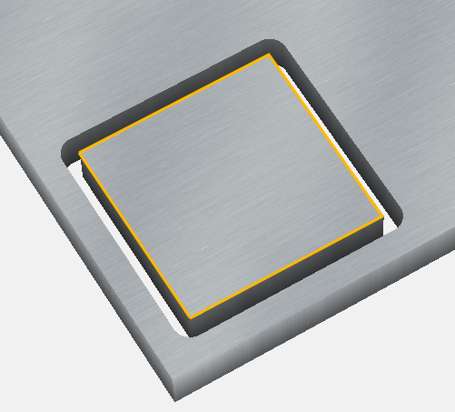
a Toolpath corresponds to a milling operation where the endmill movement is constrained by a given (closed) shape. Taking the example of a square shape:
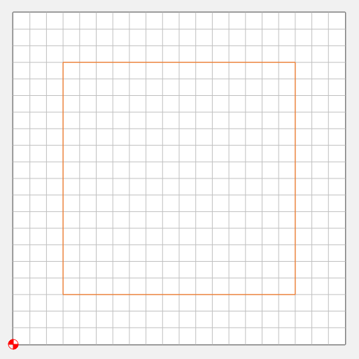
Various types of toolpaths can be created based on this reference shape (highlighted in yellow in the following pictures):
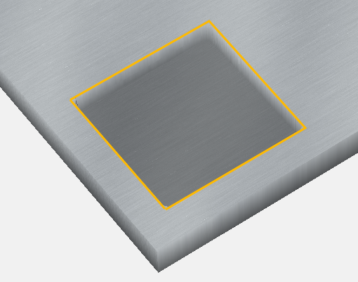
-
a very common one is a pocket operation, where the endmill will move inside the shape, to empty material starting from the surface and down to a predefined depth:
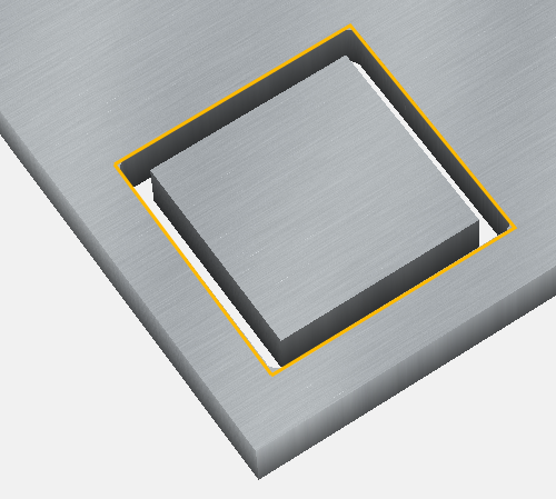
-
another typical operation is an outside contour, where the endmill cuts material along the outside of the shape, so you are left with a cut out piece of the size of the original shape
-
conversely, with an “inside contour” you are left with a hole of the size of the original shape:
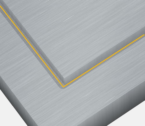
-
finally, the no-offset contour makes the endmill move centered along the shape lines:
-
V-carve is a specific toolpath, which is vaguely similar to a pocket but with sloped borders, it is intended to drive a V-bit of a given angle on the inside of the shapes (text letters, most often)
Overall toolpath
A design usually contains many shapes and their associated toolpaths, but in the end the CAM tool generates a single set of sequential G-code instructions to be run by the machine, so it executes all the toolpaths in sequence.
G-code preview/visualization
When using a CAM tool like Carbide Create that does not have a preview of the complete toolpath, it is a good idea to check the generated G-code to see what it will do, before loading it in the shapeoko. There are many G-code viewers out there, I like this simple one and just copy/paste the G-code I want to check. Fusion has an integrated preview, which is nice.
Feeds and Speeds (theory)
So now I had a machine that was able to move a spindle rotating an endmill cutting into stock material. An important question was how fast should the endmill be turning and moving into the material. Seasoned CNC machinists apparently have a whole range of rules, databases, and tools to figure this out, but here are my beginner’s notes :
- RPM (revolutions per minute) is the rotation speed of the endmill, with the Makita router it is between 10.000 RPM and 30.000 RPM
- an endmill has a given number of flutes that bite into the material at each rotation (if the endmill is moving, that is)
- the larger the diameter of the endmill, the faster the linear speed of a cutting tooth into the material
- the feedrate is how fast (inch or mm per minute) the endmill moves into the material (or how fast the material is pushed into the endmill, for CNC machines like the Nomad that move the object, not the spindle)
The name of the game is to find just the right combination of endmill type (diameter & number of flutes), RPM (set on router), and feedrate (set on CNC machine) for a given material to be milled, to achieve efficient cutting:
- A high RPM and slow feedrate can result in cutting very thin chips at every rotation, which is a problem:
- milling will take a long time
- but more importantly, the cutting generates heat on the cutting teeth (and the material) by friction, and the amount of heat that gets removed from the end mill is linked with the thickness of the chip being removed. So very thin chips means that almost no heat dissipation occurs, the heat builds up on the endmill, and this quickly ruins it, ending up in poor quality cuts and a damaged tool.
- A low RPM and high feedrate can lead to excessive force applied on the bit/machine axes/motors, and end up breaking the bit or damaging the machine itself.
So for each situation there is a sweet spot combining the right endmill, RPM, and feedrate. There is this chipload value that represents just that, and is computed like this:
Chipload = FeedRate / ( NumberOfFlutes x SpindleSpeed)
sometimes the endmill diameter gets added in the formula too to include linear speed of the cutting teeth. But anyway, the important thing I think is to understand the dependencies between these variables (i.e. which parameter to vary in what direction to increase or reduce the load or speed), then there are plenty of online and offline tools to compute feeds & speeds for you. As a beginner, I used what Carbide Create gave me as a starting baseline for a given material & selected endmill.
Initial milling tests
Next step was to start some actual milling !
1st test : milling Depron
I wanted to start with a very soft (i.e. forgiving) material, and I had some depron foam at hand, so this looked like the perfect stock to practice on. I used a very basic pattern in Carbide Create (source file is here, corresponding G-code is here), zeroed on the surface, and hit “Run”:
So far, so good. Edges are not very clean, but the intent was not to optimize feeds & speeds on this one.
2nd test: engraving
As a learning exercise and test, I decided to engrave the metal tag that ships with the Shapeoko. Since I would need to get it right in a single run, I tried it beforehand on an old plastic membership card:
I used a “V-carve” toolpath in CC, configuring for the smallest endmill in the list (0.035 inch I think), but actually mounted a small dremel (#125) cutter. I should have created a custom endmill corresponding to the dremel cutter in CC, but was lazy and for a simple engraving test this was not critical. I was quite happy with the results on plastic, so I proceeded to engraving the metal tag after adjusting text size a bit:
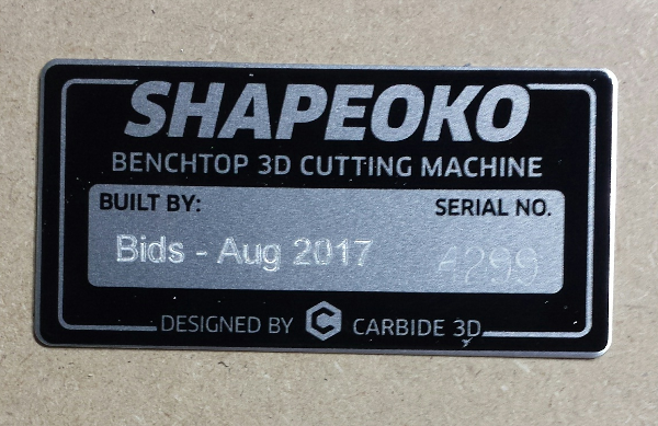
The corresponding Carbide Create source file is here, and the generated g-code is here
Enclosure
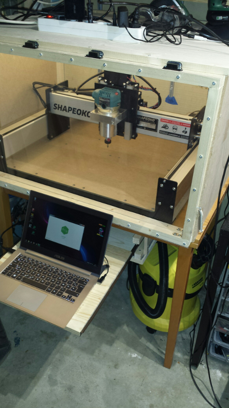
As everyone learns very quickly when starting CNC, milling is very messy (wood/metal chips everywhere!) and noisy (router spinning, vacuum cleaner running, and to a minor extent the stepper motors buzzing), not to mention slightly dangerous (who knows where this piece of broken endmill will go flying to…). So I built a very basic wooden enclosure, more or less of the the size of the table the shapeoko was resting on, with a plexiglass panel on the front. I hacked a sliding tablet underneath the table to put my laptop, close enough to connect the USB, to have things right in front of me when jogging the machine.
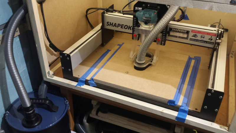
Here’s a view of the setup:
I later added foam on the inside walls for sound proofing:
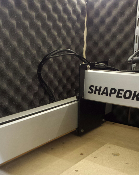
Overall I’m happy I built the enclosure very early, the noise is much lower, and it feels safe to have the plexiglas window in addition to my safety goggles (I may be a little paranoid, but better safe than sorry)
Chips/dust collection
Another thing I realized very quickly is that I would not get away with just vacuuming chips/dust manually after the milling operations, as I initially thought I could do. Even small milling operations generate a significant amount of mess, and one quickly ends-up with dust everywhere inside and outside the shapeoko. Also, regularly inhaling MDF dust is a VERY BAD idea (hint: it has the word “Fiber” in it, they might as well call it Medium Density Cancer).
So, I investigated options for installing a permanent vacuuming system. The typical solution is to install a “dust shoe” attached to the spindle, plug a hose in it, and use a vacuum cleaner on the other end. There is always the option of creating a DIY dust shoe, but this time I had neither time nor desire to do it, so I went for buying the Suckit dust boot, that is designed specifically for the Shapeoko3.
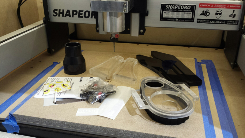
I had to bite the bullet again (87$ + shipping), but I must say I have zero regret, it is worth the price considering the added value, its sturdiness, and the fact that a lot of thought went into the design to make it convenient to use. Here is a view of the kit as received after unwrapping all pieces (all very well protected individually in the shipping box) :
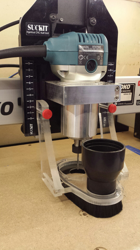
And here it is assembled onto the shapeoko:
For the vaccum part, I went for
- buying a (very) cheap regular vacuum cleaner with variable power: it turns out there is no need to run it at full power and using the lowest power setting is enough and is much less loud. I had initially used my Karcher dust vacuum cleaner, but it is just way too loud to endure for more than 5 minutes.
- adding a dust bucket in between the dust shoe and the vacuum cleaner: this is where most of the filtering happens, and it allows to very easily empty the bucket:
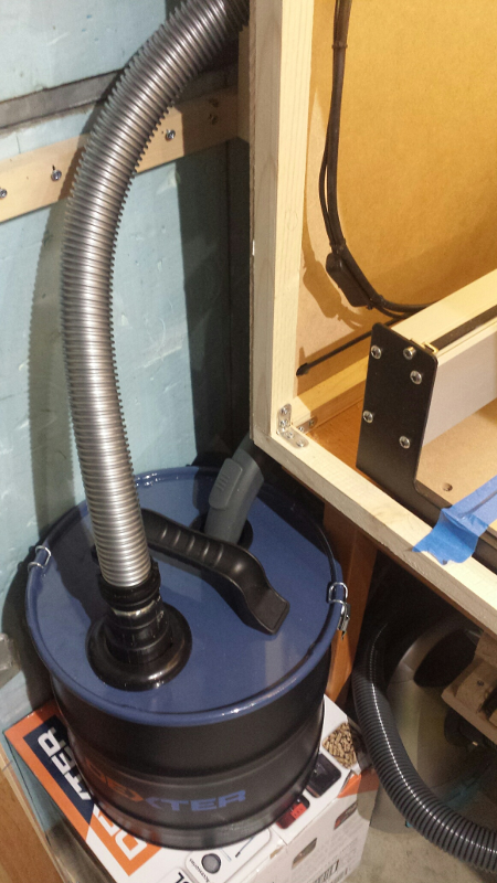
Here is a view of the full setup:
It was good enough as a starting setup, but after I while during long jobs I realized a significant part of the chips/dust was passing through the bucket and into the vacuum cleaner dust bag. Which is not good for the vacuum cleaner itself, and had me swap the dust bag regularly, so I upgraded to a more efficient solution : I ordered a cheap (16$) cyclone dust collector, and fastened it onto the bucket:
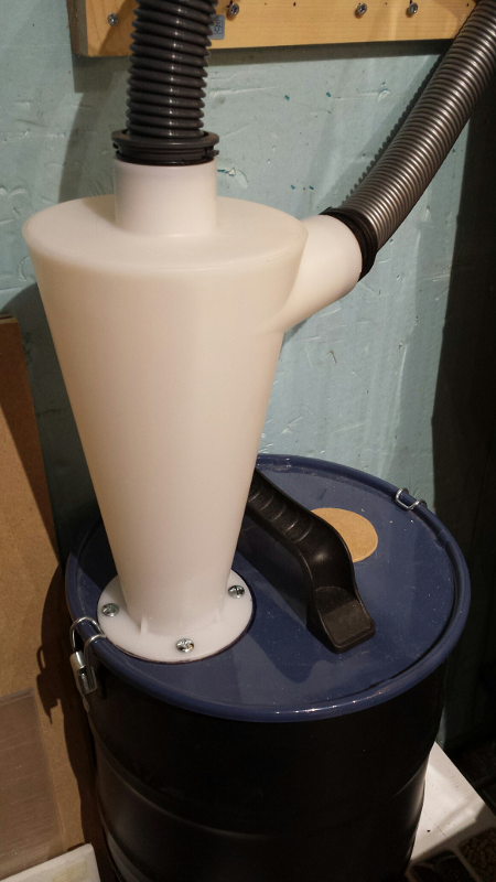
The hose from the dust shoe is the horizontal one, and the hose to the vaccum cleaner is the vertical one on top. It’s a glorified piece of plastic, but is very efficient at separating chips & dust from the air. Here’s a short video of the cyclone in action, you can literally see the spiral of chips being sucked through it and down into the bucket:
Making a wasteboard
The wasteboard is the flat piece of material that is attached on the bed of the CNC, will allow to secure the object to be milled, but more importantly is there to provide margin between the bottom of the milled stock and the bed of the CNC. Most milling projects drive the tool down to the max depth of the stock, e.g. to cut out shapes or mill through-holes, so without a wasteboard, the shapeoko MDF bed itself would be scratched (or ruined, in case of a major error on the depth of the toolpath being executed). The wasteboard on the other can easily be replaced when it is too damaged.
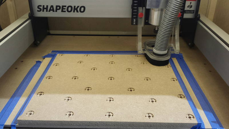
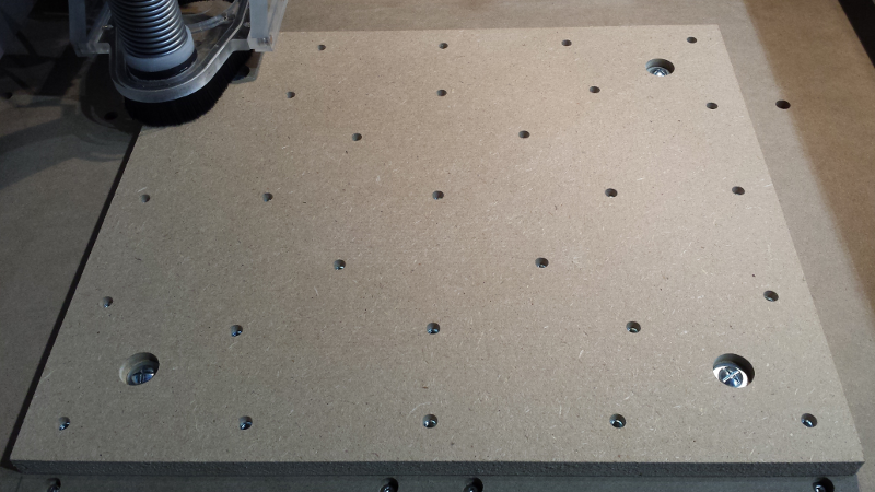
I went for a typical square-ish MDF wasteboard with inserted T-nuts. Making it is in itself an excellent exercise to practice designing and running a milling job.
design
In Carbide Create, I defined a 400mm (width) x 350mm (depth) rectangular stock (I initially went with 400m on both sides to get a nice square, but it turns out that the shapeoko cannot quite reach a Y value of 40cm from the front of the machine).
I had these M6 T-nuts on hand:
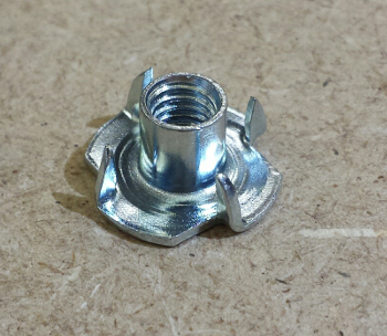
so I measured them, and designed a hole pattern accordingly to receive them:
- 7.5mm diameter through-hole: this would allow to insert the T-nut body, and insert the M6 screw for securing the object from the other side.
- 19 mm diameter counterbore, depth=2mm: this would accomodate the head of the T-nut.
- 4 x (4mm diameter pocket), depth = 4mm : this would accomodate the four teeth of the T-nut (after a few tests trying to hammer T-nut teeth into the MDF, I chose this approach to have a very clean/flat insertion, without making the MDF bulge due to pushing the teeth in).
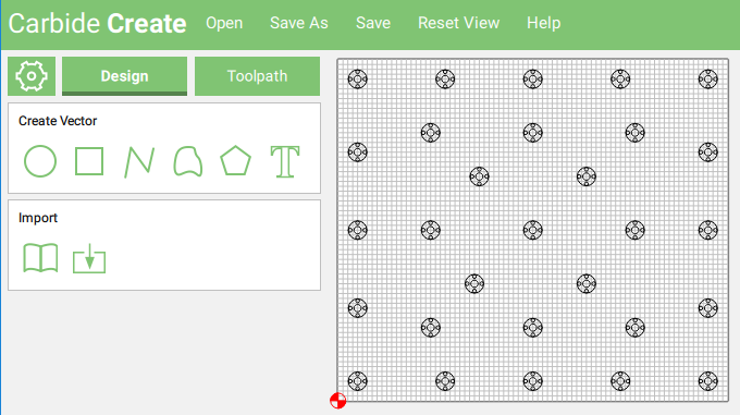
I then copy/pasted this as many times as needed to cover the whole underside of the wasteboard, using a reasonable step (to keep the number of T-nuts below ~30) and a pattern I liked (not quite regular, but not optimized either, there are some much better patterns being discussed in forums)
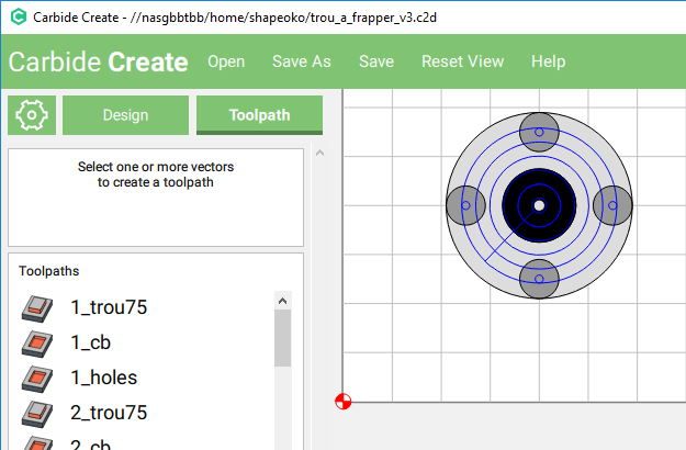
I initially created three toolpaths in Carbide Create (one for the main hole, one for the counterbore, one for the four mini-holes), and applied each of them to all corresponding shapes (using the Ctrl key to multi-select shapes while in editing mode of the toolpath), but when I previewed the generated G-code, I realized this approach produced a highly inefficient run where most of the milling time was spent moving the endmill, and consequently the total runtime was crazy (1.5h) :
So instead I created three individual toolpaths for the first hole, created three more (identical) for the second hole, etc… and so on or the 29 holes, and previewing the resulting G-code showed an optimized path and a much more acceptable run time of 38 minutes :
(yes, I also changed the number and positions of the holes while I was at it, so it is not completely fair to compare them, but the difference is still obvious)
Of course, creating the 29 x 3 toolpaths manually in CC was very tedious, and silly to do anyway because it meant that any potential change would need to be applied manually at least 29 times. I learned my lesson: next time, I will do this either from a more advanced tool that can optimize toolpaths better, or make a design for a single hole and replay it manually at different positions, through scripting or something.
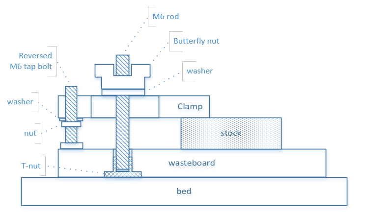
One thing that was not quite obvious to me first, is how to secure the wasteboard itself onto the shapeoko MDF bed. I chose to create four countersunk holes to insert the screws that would go into T-nuts placed on the underside of the shapeoko bed. However, since I really did not want to disassemble my shapeoko bed just for this (and then having to redo the machine squaring…), I went instead for using another kind of T-nut with no teeth, that I could insert from underneath the shapeoko without having to machine anything from the underside, a simple drilled hole would do:
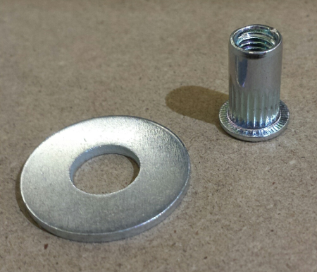
Since this model of T-nut has a very narrow head, I added a washer to have a large surface to pull on.
The Carbide Create source file is here. I generated two corresponding G-codes (since total milling time is about 40 minutes, I wanted to execute the first half and second half independently), they are here and here.
On the top side, I just needed a through hole with a countersink, to place a large washer, and the M5 screw going down into the T-nut underside the bed:
- 7mm diameter through hole
- counterbore: 20mm diameter + 7mm depth
The Carbide Create source file is here and the generated G-code is here.
Milling the wasteboard
For milling, I used a 1-flute square 3.175mm end mill, so I first created this tool in Carbide Create with the following caracteristics:
- Diameter: 3.175mm
- Flute length: 20mm
- Number of flutes: 1
Based on these, for milling into MDF material Carbide Create computed a depth per pass of 1.2mm, feedrate of 654mm/min, and 15.000RPM for the router (i.e. Makita control knob halfway between 2 and 3). Here is the result after running the two halves, for a total runtime of about 40 minutes:
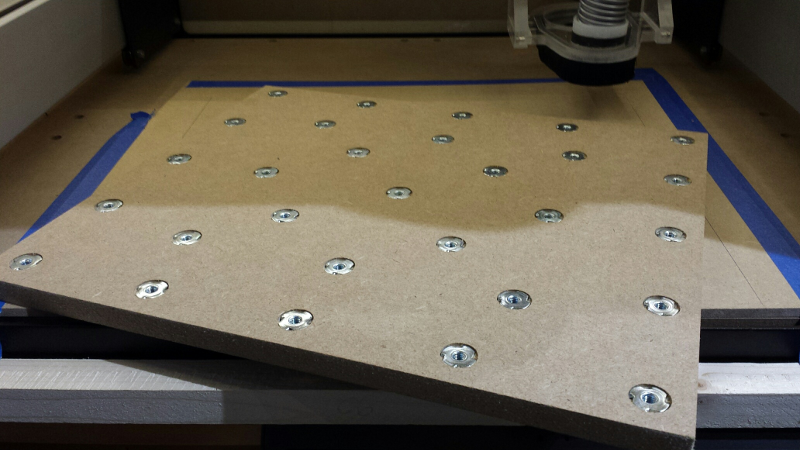
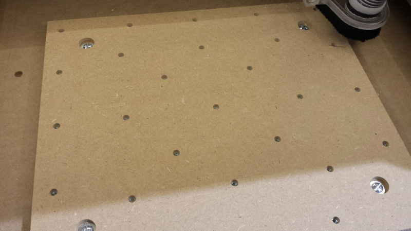
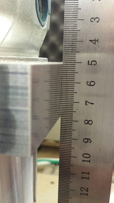
Here it is after assembling the T-nuts, and verifying by moving a ruler across the board that none of them sticked out above the surface:
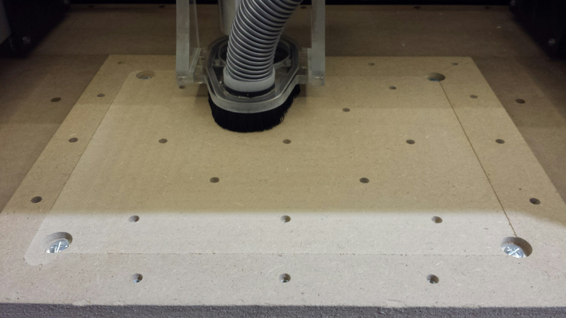
I then flipped the wasteboard, placed it in its final position on the shapeoko, manually marked the four spots for securing it, removed the wasteboard and drilled four corresponding holes in the bed, inserted the T-nuts from the underside, and finally secured the wasteboard onto the bed with M5 fasteners:
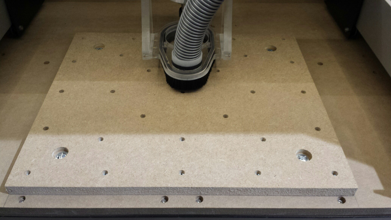
There is approximately 5mm of margin of MDF between the top of the T-nuts and the surface, which should be enough to allow a few resurfacing passes over time.
Surfacing
Due to mechanical assembly/imprecisions, and subtle variations in the thickness of the wasteboard, it is quite likely that the surface of the wasteboard is not perfectly parallel to the X/Y plane of the machine, which can result in visible differences in height on different sides of a large milled piece. To correct this effect, an easy way is to surface the wasteboard, i.e. to run a square endmill at a constant (and very shallow) depth across the whole area of the wasteboard: by definition the resulting top surface of the wasteboard will then be perfectly aligned with the X/Y plane of the machine.
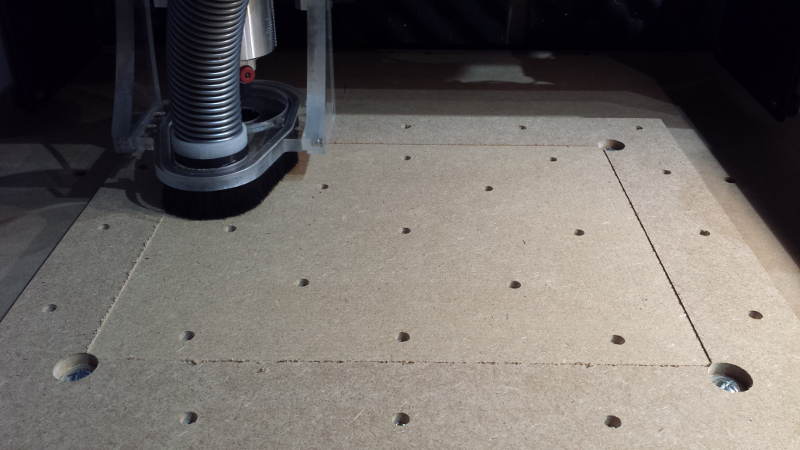
I ordered a proper surfacing endmill, but since it was still on its way I used a regular 6mm square endmill and practiced over a 10x10cm square, with 0.75mm depth:
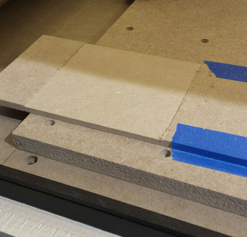
That looked fine, so I proceeded to apply the same operation to the whole wasteboard.
Murphy’s law
I was in the middle of zeroing the machine before starting the surfacing job, when out of the blue s**t happened: the machine stopped responding, and a few seconds later I smelled an acrid smell of burnt plastic. Oh-oh. That couldn’t be good. After unplugging everything and unmounting the controller shroud, I discovered the sad reality: one of the four stepper drivers on the controller had just died in a puff of smoke:
MAJOR bummer, especially since I was being extra careful, and at the time this happened I was nowhere near any mechanical limit, the mill was still in the air, nothing was moving, the router was off, there was absolutely zero reasons for anything to go bad.
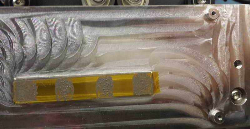
I disassembled the board, the heatsink looked ok (the kapton tape is there on purpose to isolate the board, while still allowing the thermal conduction between the heatsink and PCB),
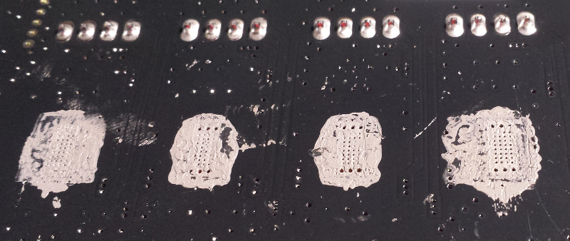
And the underside of the board looked fine too, no obvious issue (e.g. lack of thermal paste) there:
So I’ll never know what happened exactly, but after the initial issue with reset not working on this controller board, I suspect I got a bad board somehow or was just unlucky. Anyway, I contacted Carbide3D’s support, and they shipped a replacement board on the same day, so again very efficient support!
Migrating to Fusion360
While I was waiting for the replacement board, I decided to start learning Fusion360. While I am sure that it will still take hundreds of hours to master it, I was pleasantly surprised to find out that it was not that hard to understand the basic workflow and start creating objects and toolpaths. I watched the 60-minutes worth of introduction videos from Adobe’s web site to get to know the features, and a couple of tutorials later I had a (very) basic understanding of what I was doing, so it was encouraging.
I captured my beginner’s notes in this Fusion360 survival guide
Back to surfacing
After receiving the replacement board I re-assembled it onto the heatsink, after putting a (very) small drop of thermal paste behind each driver chip, and I was good to go.
So, back to surfacing the wasteboard:
I captured a small video in the middle of the execution (turn the volume down!):
And here is the resulting surfaced wasteboard (which obviously does not look any different, but at least has its top plane parallel to the machine XY plane now):
Workholding
Ok, so I had a surfaced wasteboard, but I still lacked clamps to secure the stock material onto the wasteboard using fasteners into the threaded T-nuts. It seems like the topic of workholding is a rabbit hole in itself, so I tried to not get sucked into that too much, and here is my beginner’s take on things:
- I will start with wooden clamps as many do, since:
- it will be more forgiving the first time I crash the endmill into them for some reason
- I will only be milling wood & plastics for the foreseable future, so this should be good enough, an extremely sturdy workholding solution is not yet mandatory for me.
- I will probably buy quality clamps somewhere down the road.
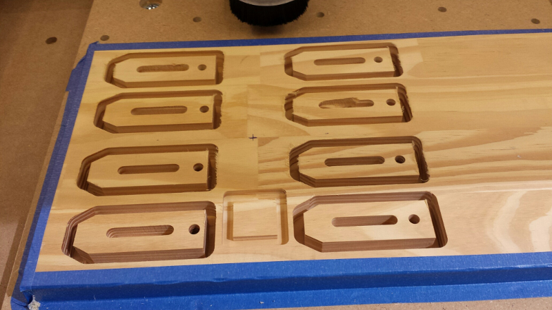
So, to avoid overthinking it too much I reused the design from the Shapeoko clamps tutorial, and customized it a bit :
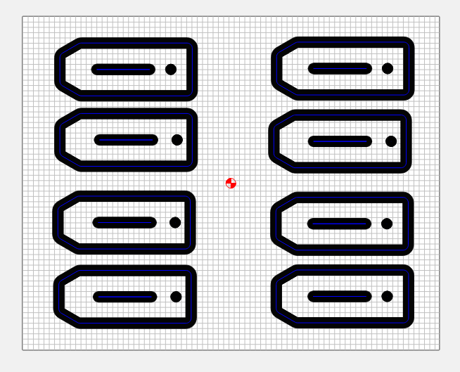
(the project file and generated G-code is here)
Since I made them out of wood instead of high density plastic like the original tutorial, I could not thread the back hole so I went for a slightly different approach:
Of course, holding the stock out of which the clamps will be milled is a bit of a catch22, I used blue painting tape on all four sides which secured the stock in a very tight way actually:
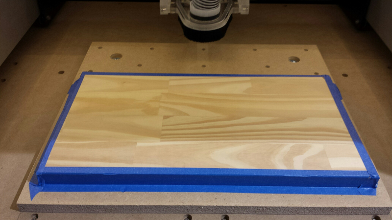
Then came the time to mill. I used a 1/4” square endmill, and pretty much the default settings from CC for “Soft Wood”, but I had not anticipated that the stock I used would be so hard, and my initial runs went horribly wrong:
-
the first time I run the job, I had not pushed the endmill far enough into the collet and/or not fastened it strongly enough, and in the middle of the job the whole thing began to vibrate/chatter, and in the one second it took me to hit the emergency stop, the 1/4” endmill got loose and went out of the collet. VERY scary stuff, I’m glad I had the dust shoe on and my safety goggles.
-
I secured it better, and with rattled nerves restarted the job: better, but still I did not like the sound the mill made now and then, so I stopped it and reduced the feedrate.
-
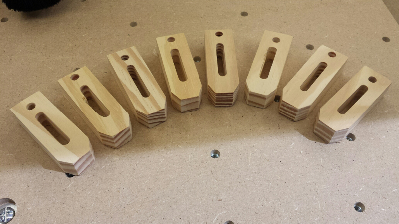
third time’s the charm, with the following more conservative settings I was able to get a clean cutting sound and complete the job without further issues:
- 15.000 RPM
- feedrate 700mm/min
- plungerate 200mm/min
- depth per pass 2 mm, stepover 1 mm
A bit more manual work to detach the clamps from the stock and clean-up the edges, and I had my first clamps:
So, LESSONS LEARNED:
- make sure enough of the mill’s shank is inserted inside the collet, and fasten the mill tightly (not too much either…)
- different pieces of wood that look the same can have very different hardness.
- start with conservative chipload setting, do some trial runs, and raise slowly.
- this is when I first considered buying G-wizard or equivalent to kickstart the process with reasonably good values for a given material and endmill.
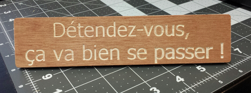
V-carving a small plaque
As an exercize to practice V-carving and put my 60° V-bit to use, I designed a small plaque to be milled from plywood:
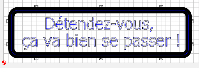
Since I would cut out the plaque completely from the stock, I added holding tabs (the checked boxes on the screenshot) using the associated Carbide Create’s feature. Given the experience with the milling of the clamps, I set conservative values for the feeds and speeds, :
- 12500RPM
- Feedrate 1000 mm/min
- Plungerate 200mm/min
Result after running the job:
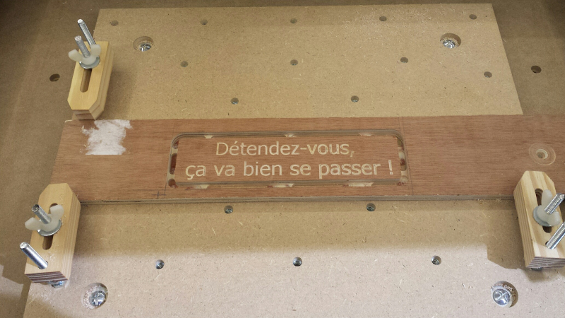
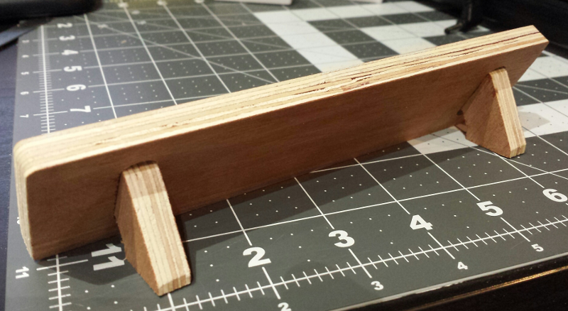
I then cut the piece from the stock and did a little clean-up/sanding of the remains of the tabs. Finally, I created two additional CC files to create two small feet for the plaque, and the some corresponding slots to fit them on the back of the plaque :
The bottom of the carving is not perfectly clean, but considering this was a first try, good enough.
All the CC project files and generated G-codes are available here.
Feeds and Speeds (Practice)
Case #1: milling Pine wood
So, I tried to figure out the proper feedrate & speed for the following usecase:
- material = Pine wood, of the harder kind (hardness varies a lot between types of pine, beware!)
- endmill = 1/4” (6.35mm) square endmill, 3-flutes
Creating a blank project in CC, setting material to “hard wood”, and selecting the #201 bit (the 1/4” square endmill) gave me :
- Depth per pass = 2.345mm
- Feedrate = 1905 mm/min
- Plungerate = 476mm/min
- RPM = 12500
That’s a Chipload of 1905/(15000*3) = 0.0508 mm
On the other hand the Shapeoko3 feed & speed chart has an entry for “pine” for the 1/4” 3-flute endmill, that recommends these settings:
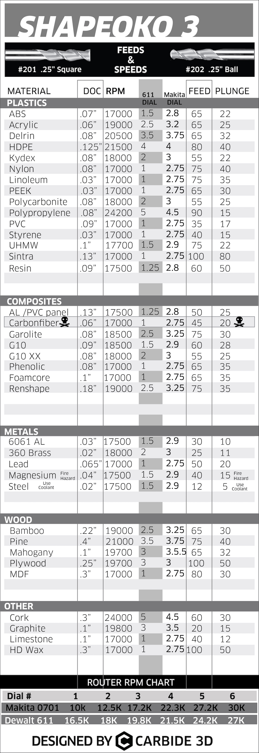
- Depth per pass = 10.16mm (0.4”)
- Feedrate = 1905 mm/min
- Plungerate = 1016 mm/min
- RPM = 21000
That’s a Chipload of 1905/(21000*3) = 0.030 mm
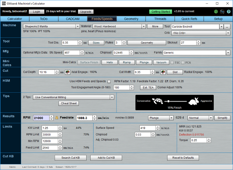
I registered for the free trial of G-wizard, and re-created a close setup, fixing the DOC to 2.345mm and 10.16mm respectively, fixing the RPM as per values above, and then adjusting the aggressiveness setting to have the same feedrate:
Scenario #1: DOC=2.345mm, RPM=125000

This usecase corresponds to 20% aggressiveness, which seems like a fair setting, considering the shapeoko’s limitation, and to be safe.
Scenario #2: DOC=10.16mm (0.4”)
This usecase corresponds to 15% aggressiveness, which sounds even safer, BUT G-wizard shows a warning on the tool deflection value (no wonder, given the endmill stickout of almost 30mm and for a depth of cut of 10mm)
These feedrates seemed high to me (which apparently is typical of beginners), so I experimented milling a basic pocket with various settings, with DOC between 2 and 3.5mm, feedrate between 500 and 2000mm/min, and RPM between 12000 and 21000:
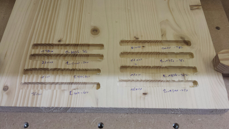
and kept a sample of the chips for each run:
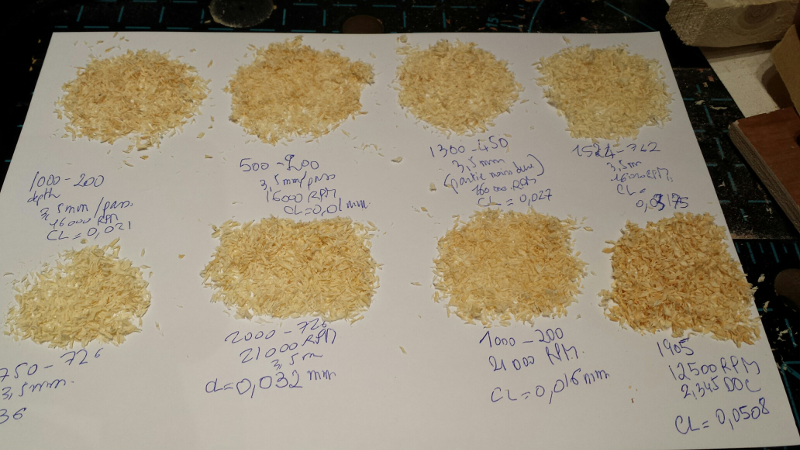
It is difficult to judge results from this picture, but my findings were:
- chiploads around 0.01mm is definitely too small: the chips do not look right, and the general look of the cut itself is not very good, and these were the cuts that produce the most chatter/unpleasant cutting sounds
- chiploads around 0.02-0.03mm are better
- chipload at 0.05mm looks the best: nice chips; and low chatter/vibration during the cut.
Lessons learned:
- CC seems to have quite decent default values
- low chipload/feedrate can be bad: I had read about the possible overheating effects when using too small values, but had not anticipated that going too slow could also produce harsher cuts and more chatter.
I did not dare trying a cut with DOC=10.16mm, since I believe this setting from the Shapeoko chart is more adequate for very soft pine wood (this indeed mentions a depth of cut of 2 times the diameter of the endmill for soft wood/pine)
Case #2 : milling plastic
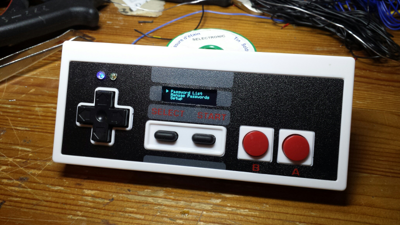
As a very first try milling plastic, I decided to use the Shapeoko to cut out some holes and a slot in the body of a SNES game controller, to make a second version for my BlueKey project.
I had cut the first version by hand, and with two small 3mm LEDs and the OLED display mounted it ended up looking like this:
I measured the required distances from the bottom left corner of the controller, and created a Carbide Create project to mill two 3mm holes and the display slot at the right location:
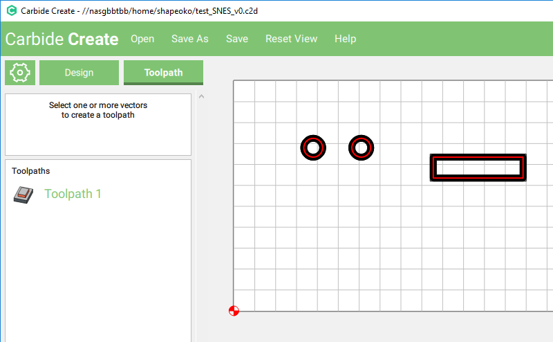
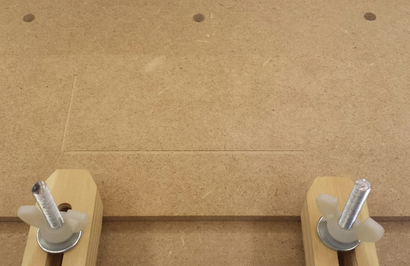
One concern was how to make sure the slot would be milled parallel to the border of the controller body, so I first milled a set of shallow perpendicular pockets aligned to the zero of the project:
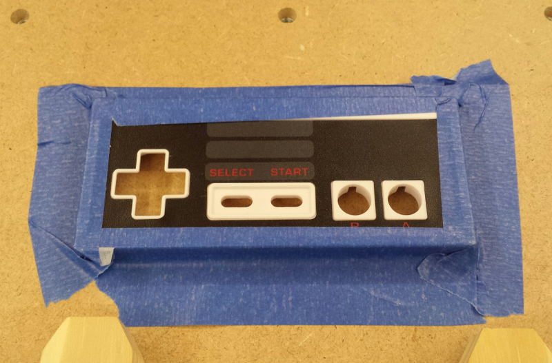
Then aligned the SNES controller on these axes, and taped it down:
I used a 1.5mm 2-flute straight endmill, played around a bit in G-wizard to determine feeds and speeds selecting “Hard Plastic” as the material, and settled on this:
- RPM = 12000
- Feedrate = 250 mm/min (33% on the tortoise-hare slider in G-wizard)
- depth of cut = 0.2mm
Milling went fine most of the way, but in one of the very final passes, the bit broke…
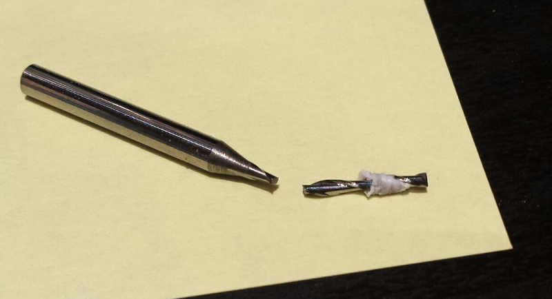
Deflection did show up in red in G-wizard at 0.02mm, but I think the issue was more due to the plastic melting and sticking to the endmill, eventually covering the cutting edges while the spindle continued moving…
Anyway, after a bit of manual finishing/clean-up, I ended-up with this:
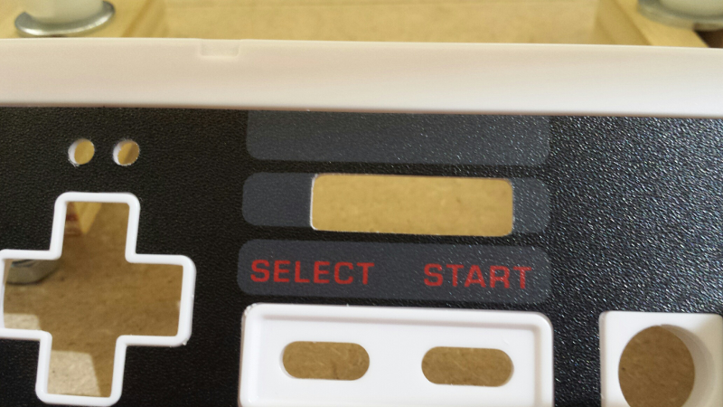
Good enough, but I obviously did a mistake while measuring dimensions to align the display slot.
Lessons learned:
- small bits and plastic…probably not the easiest combination to experiment with as a beginner
- I still need to figure out if my calculated feed rate was really too slow (hence the melted plastic)
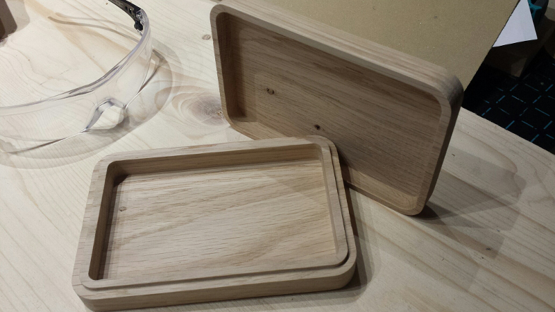
Case #3: basic wooden box
Next up I tried to make a very basic wooden box, out of pine wood. Just a few filleted rectangles in Carbide Create:
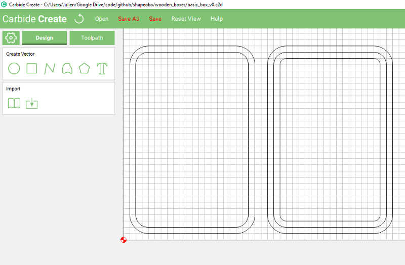
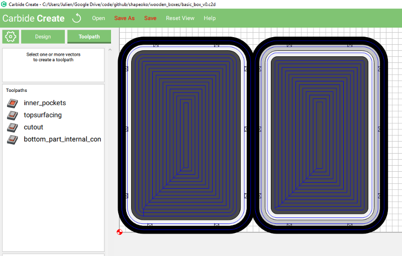
And the toolpaths to mill the inside pockets, surface the joining planes, and cutout the bottom and top parts (with tabs to hold the pieces in the stock)
Parameters (used as is from CC):
- 1/4” 3-flute square endmill
- RPM = 12500
- Feedrate = 1905 mm/min
- depth of cut = 2.814mm
- Plungerate = 365mm/min
I used a caliper to measure the thickness of the stock, it happened to not be very uniform, I entered the max value I measured in CC.
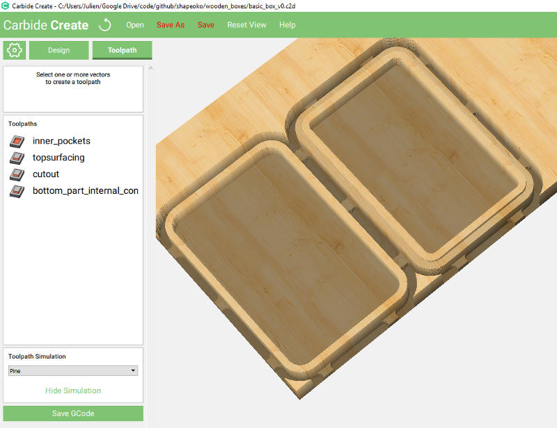
Simulation looked as expected:
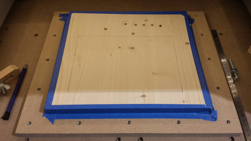
So I proceeded to install the stock material. The problem I kept running into is that the dust shoe takes a lot of space, and I could not fit the clamps in such a way that they would not collide. So back to basics: paint tape. For pine wood and this kind of job, and if using tape on the four sides of the stock, over time I keep concluding that it is quite ok:
28 minutes later, the job was finished. I had to pause the job a few times, since large chunks of pine had accumulated in the corner of the dust shoe, and after a while the vacuuming was not good enough.
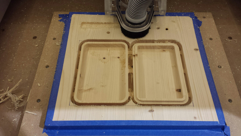
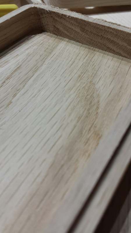
Removing the stock, I was happy to see that uniformity of the cut was not that bad, given the initial variations in the stock. Only a very thin layer of wood remained in some areas:
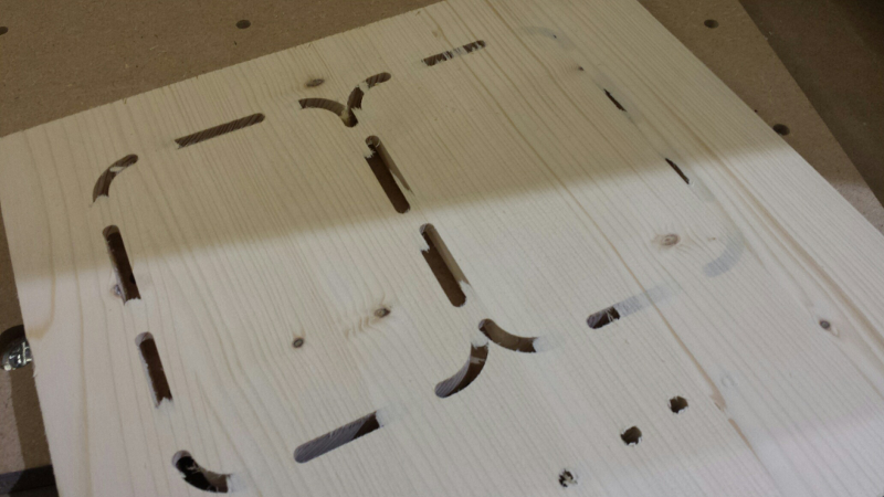
and there was no visible marks on the wasteboard surface, so I was spot on for depth:
After cutting the tabs, cleaning-up and sanding both parts, I got this:
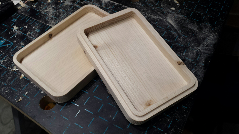
And was happy to see that the two part fitted just right: so even my uncalibrated machine did a very decent job already.
Lessons learned:
- When milling fast in pine in the direction of the grain, the endmill has a tendency to rip long thin strips of wood instead of individual chips, which can accumulate in the dust shoe and cause trouble. I should try with a slightly lower feedrate to see if this still happens, and/or try a downcut endmill to see if the effect is the same.
- Pine + upcut endmill = lots of manual clean-up afterwards.
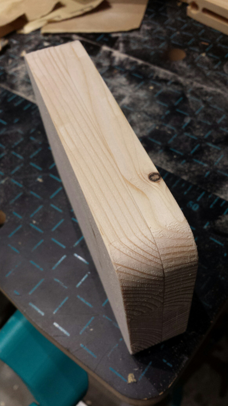
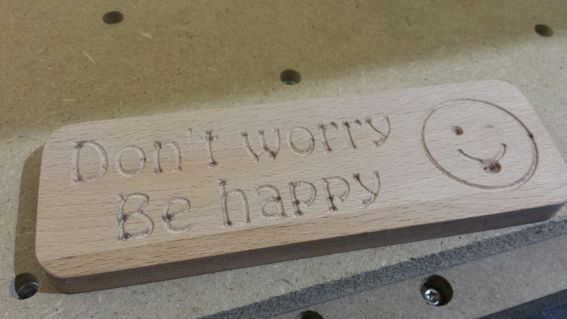
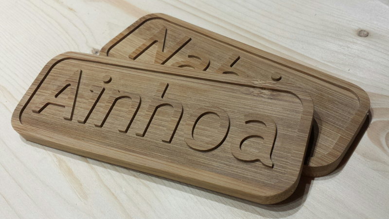
Case #4 : hard wood plaques
For this next case, I wanted to give a try to milling hard(er) wood, and use the opportunity to build small plaques for friends. I found a Beech wood cutting board at a nearby store, and decided to use it as stock to cut two small plaques.
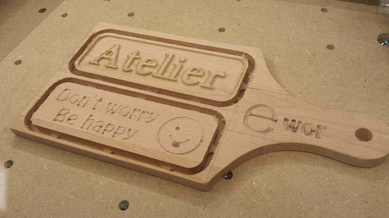
The text and sign were milled using a V-carve toolpath, and an outside contour toolpath was used to cut the plaques from the stock.
Pocket (1st plaque & panda):
- 3.175mm 1-flute square endmill
- RPM = 12500
- Feedrate = 457mm/min
- depth of cut per pass = 0.7mm
V-carve (2nd plaque):
- 90° V-bit
- RPM = 13500
- Feedrate = 1100mm/min
Cutout:
- 6mm 2-flute square endmill
- RPM = 12500
- Feedrate = 1905 mm/min
- depth of cut = 1mm
I used (strong) double-sided tape to hold the stock in place, and even for hard wood like this it worked remarkably well.
After cutting tabs and some clean-up/sanding, the first plaque came out nicely I think:
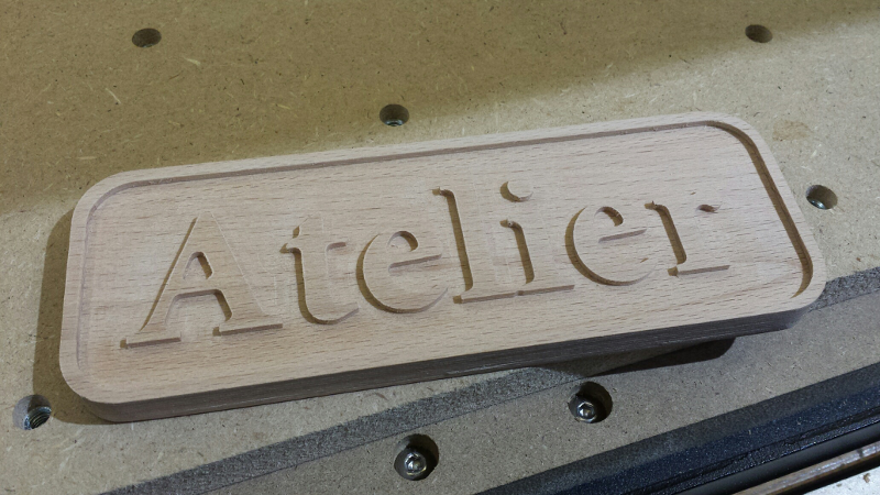
I was a bit scared of the feedrate value CC produced for the outline cut, and reduced the depth of cut to be on the safe side. The cut was quite smooth at that feedrate, so I may try pushing the DOC a bit further next time.
I painted the front of the plaque, let the paint dry, and then sanded the top (edge & letters), which gave me this:
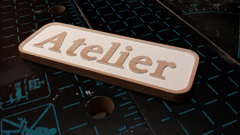
I messed up the painting part in the process, but anyway I got a chance to experiment with two-tone design, and for a door tag this turned out to be good enough.
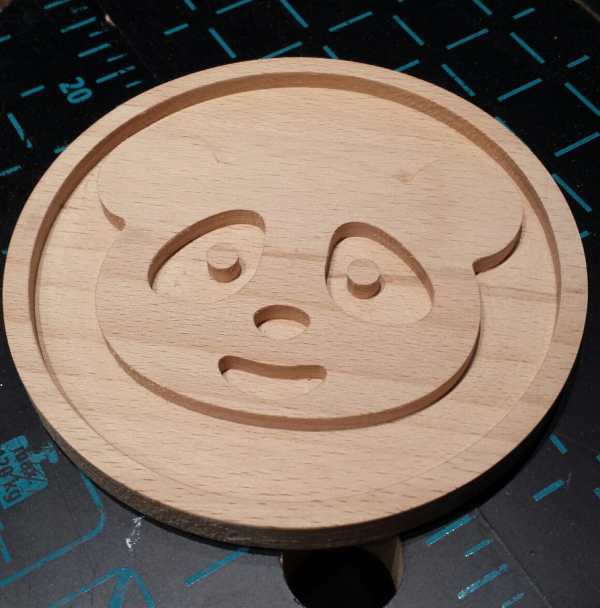
I was not very pleased with the quality of the V-carving of the second plaque though:
Even though I felt the feedrate was relatively high already, I suspect it was not high enough, and the darker spots are probably due to rubbing of the V-bit for a bit too long at that place.
Again I tried a two-tone thing, spray painting the front face, letting the paint dry, and then sanding the surface:

Clearly, there is an issue with the right side of the smiley face. It turns out it is shallower than the left side, so I will have to look into that (the original cutting board had depth differences from the start, this might be it)
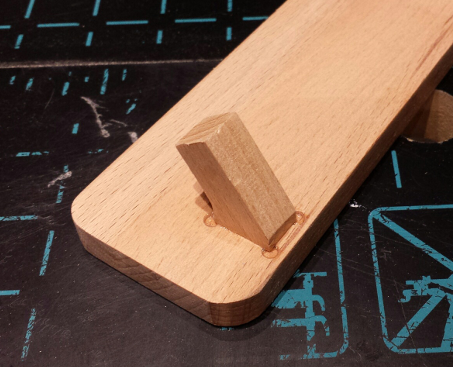
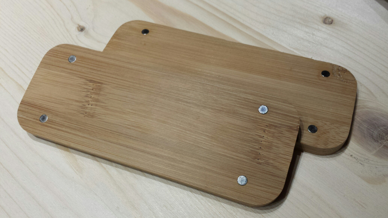
I cut two small feet and installed them in the back, to have it stand as a desk ornament:
Finally, something I did as a random way to use the remaining of the Beech stock I had:
(legalese: credits go to [Freepik] from www.flaticon.com)
And I tried some black & white painting:
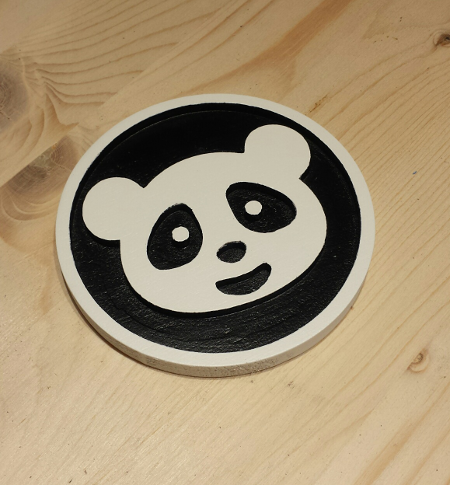
I spray-painted it white, then applied masking tape over the areas that were to remain white, cut the masking tape flush on the borders, and spray-painted it black. This turned out to be more messy than expected, and the black/white frontiers are irregular, so the ends results looks a bit “meh”. I actually liked it better raw in fact.
Lessons learned:
- surprisingly, milling Beech or Bamboo turned out to be less eventful than milling pine. I started trusting CC and G-wizard scary-high recommanded feedrates, and used DOC as a much better way to keep it safe.
- again, I’m surprised by the quality of the cut I get from my (yet) uncalibrated machine. The bottom of the “Atelier” plaque pocked barely showed any marks of the toolpath, and the letters outlines were quite sharp and nice (until I messed up the painting, that is)
- either I got the V-carving settings wrong, or my cheapo ebay V-bit is not sharp enough. I’m inclined to think it is the latter, it does not even look sharp…
- I need to work on my painting skills…a lot.
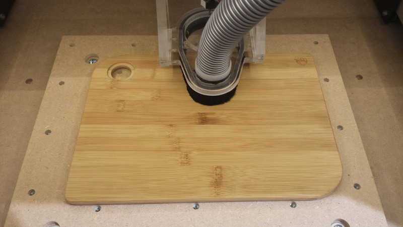
Case #5 : bamboo
Finally, I experimented with milling bamboo, which turned out smoothly:
Settings:
- 3.175mm 2-flute square endmill
- RPM = 12500
- Feedrate = 930mm/min
- depth of cut per pass = 0.7mm
(CC default values were 6250 RPM and 467mm/min, I just doubled each to meet the min RPM of the makita, while keeping the same resulting chipload)
I also milled a few 5mm wide by 2.7mm deep pockets in the back, and glued small magnets in them:
While I was at it, I did a few coasters, and tried something new: using double-side tape under the positions were the shapes will be cut, and not using any tabs:
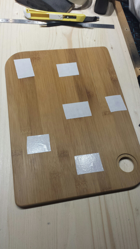
The bamboo cutting board I used as stock, taped to the wasteboard:
And after running the job:
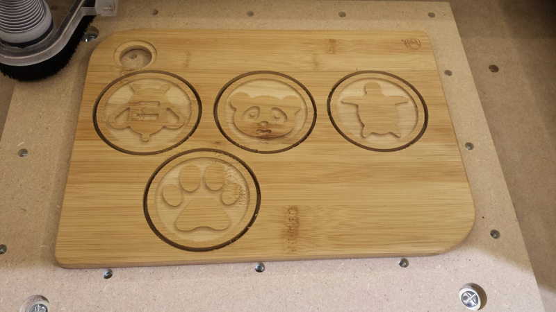
The panda one moved a bit during the very final pass (not enough double-sided tape under this one…), but otherwise things turned out pretty well:
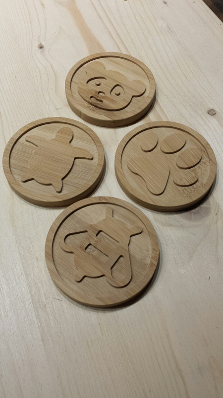
(again: credits go to [Freepik] from www.flaticon.com)
Lessons learned:
- bamboo is easy, gives very clean-looking edges, with very little sanding required.
- double-sided tape is great for milling small objects, and it is possible to get away from using tabs (and having to clean them up afterwards)
- but bamboo sticks less than some other woods, so a little rough pre-sanding before using the tape is good.
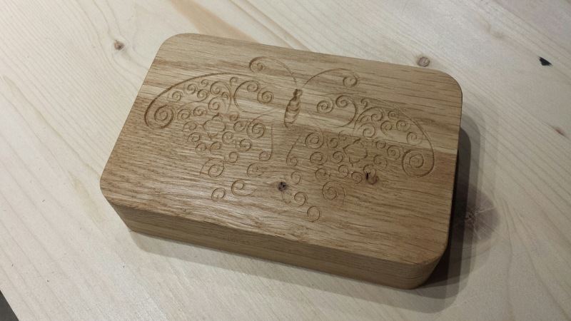
Case #6: basic box v2
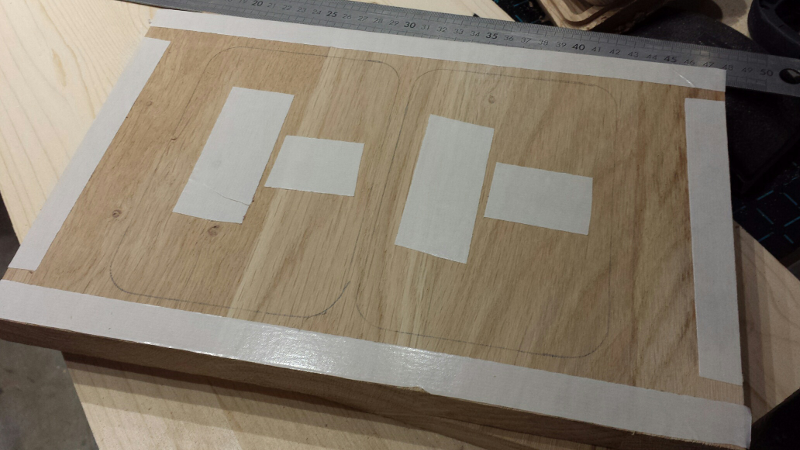
I had another go at the basic wooden box, this time with oak, and fixing a few design issues (e.g. the cover was initially thicker than the bottom part). The modified project is here.
Since this job would sure produce a LOT of chips given the size of the pockets, I needed to have the dust shoe in place, and this does not work too well with clamps, so I figured I would try double-sided tape (yes, on oak). Also, I was getting tired to using tabs and having to clean them up afterwards, so I made sure to put tape underneath the cutout parts too, got rid of the tabs, and did a full-depth profile cut instead.
I used these parameters:
- Carbide’s #201 3-flute 1/4” square endmill
- 15.000 RPM
- Feedrate 2000mm/min
- DOC 2mm
- plunge rate 200mm/min
and it turned out just fine. A little chatter now and then during the job, but nothing too heavy (and nothing that went away by reducing the feedrate, so my feeling is this must have been caused by some vibration linked to the relatively elastic holding provided by the double-sided tape).
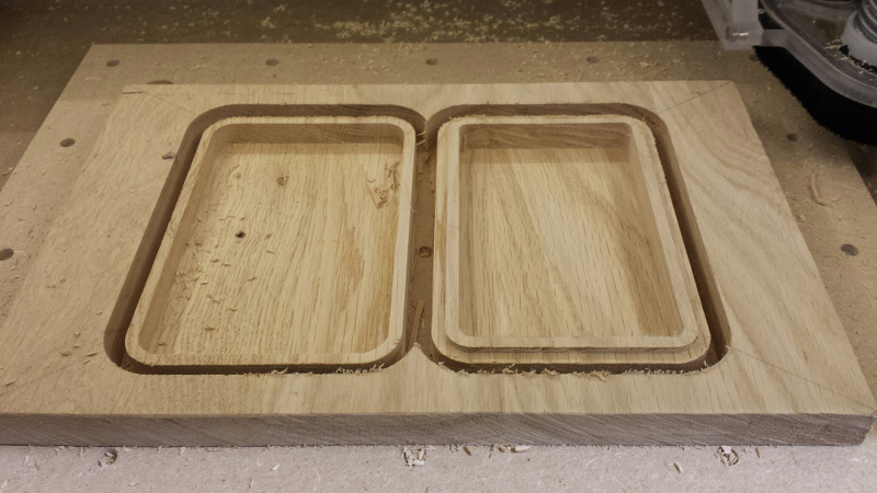
The top and bottom parts stayed in place till the end, and I had very little sanding/clean-up to do afterwards, so +1 for double-sided tape!
I finished it by V-carving a little something on the top cover, and applying tongue oil
Plunge rate and Plunge depth
Plungerate is the descent speed of the endmill into the material. An endmill is not designed to drill into material like a drill bit, so plungerate should be small(er). At this point I have not yet felt the need to optimize this parameter, so I just use whatever CC computes for me. Same for depth of cut/ plunge depth: I stick to CC’s recommandations, and in all cases I keep it below 1 time the diameter of the endmill.
Shapeoko calibration / tuning
For my current casual/beginner wood milling needs, my uncalibrated-but-decently-squared Shapeoko was fine, but in the spirit of getting better precision, I had a go at calibrating various parameters:
X/Y/Z linear calibration
GRBL uses three values referred as $100, $101 and $102, which correspond to the number of motor steps to be commanded to move by one millimeter on the X, Y and Z axes respectively.
Adjusting these values is a way to compensate for slight inaccuracies induced by mechanical play between the belt and the motor pulley, and by belt stretching.
The easiest way it to just cut a piece of a given size, i.e. 100mm x 100mm, and then measure precisely the actual X and Y size of the piece, and adjust the calibration values in the inverse proportion: By default, the shapeoko uses 40 mm/step for each axis.
$100 = (programmed X size / actual X size) * 40

$101 = (programmed Y size / actual Y size) * 40
Similarly, Z-axis can be calibrated by cutting a pocket of known depth and measuring how deep the milledp pocket actually is
$102 = (programmed pocket depth / actual pocket depth) * 40
Out of curiosity, I bought a dial indicator to figure out how accurate the spindle movements were on small distances,
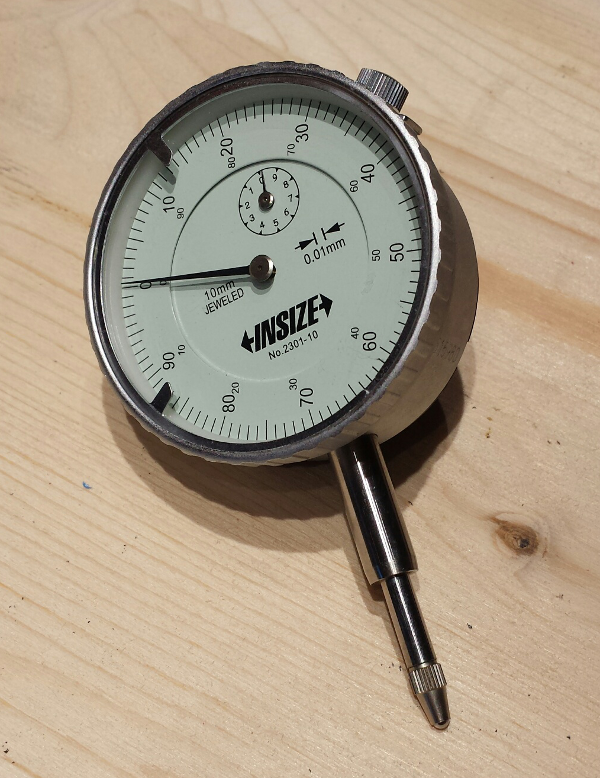
mounted it so that I could measure small scale movements :
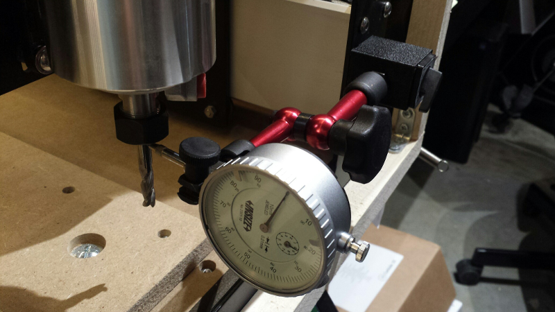
and figured out appropriate calibration factors:
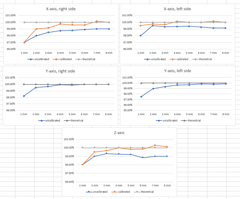
I did the same kind of tests on longer lengths (milling squares of various width and heights on a piece of scrap stock), and unsurprisingly the error is not fully linear, so one must make a choice to favor precision at small lengths or at long lengths. In the end, based on my data I picked an average ratio of 0.997 for X and 0.993 for Y, adjusted accordingly:
$100 = (1/0.997) * 40 = 40.120

$101 = (1/0.993) * 40 = 40.282
I then rerun the same job with calibrated values, and measured all dimenstions:
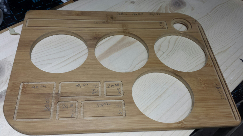
measurements before/after calibration are summarized below:
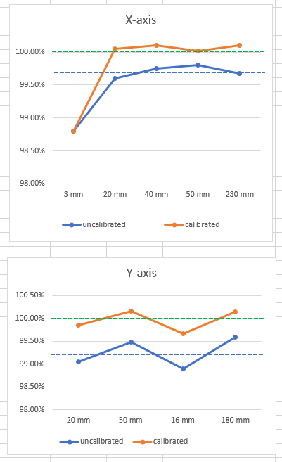
So overall I got somewhere around 0.2% error, which is more than precise enough for what I do. I’m pretty sure the measurement error and natural variations in the machine are of the same order of magnitude anyway.
Tramming/squaring the spindle
The spindle may have a slight tilt angle and not be perfectly vertical with respect to the waste board. The first time I started caring about this is when I noticed these slight stripes at the bottom of a pocket:
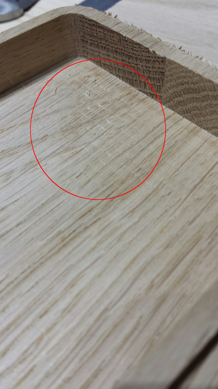
Nothing huge, but a sign that the endmill was probably slightly tilted. The fact that the stripes were only visible in one direction (corresponding to the endmill travelling along the X axis), and no visible stripes in the other direction, probably indicated that the spindle was tilted towards the front/back, but not (too much) to towards the left or right.
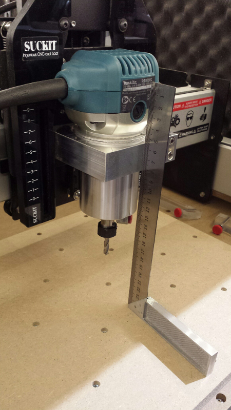
There are many ways to square the spindle (using a dedicated tramming device, a dial indicator mounted on an extension arm fastened in the collet, …), but first things first, I went for a very basic check: checking how square the spindle mount was with respect to the wasteboard. I placed a (decent) square on the wasteboard, and checked the left (and right) side of the spindle mount (to check for left/right tilt angle):
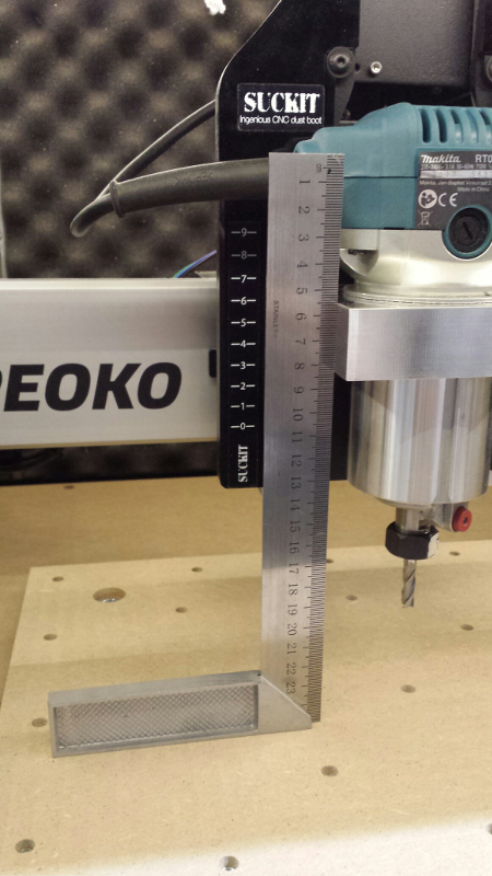
and then the front side (to check for front/back tilt angle)
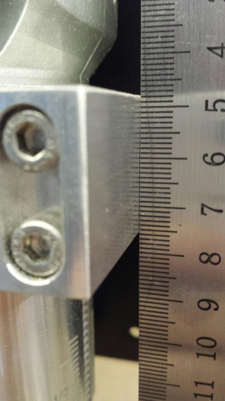
On the left/right side, the mount happened to be almost perfectly square:
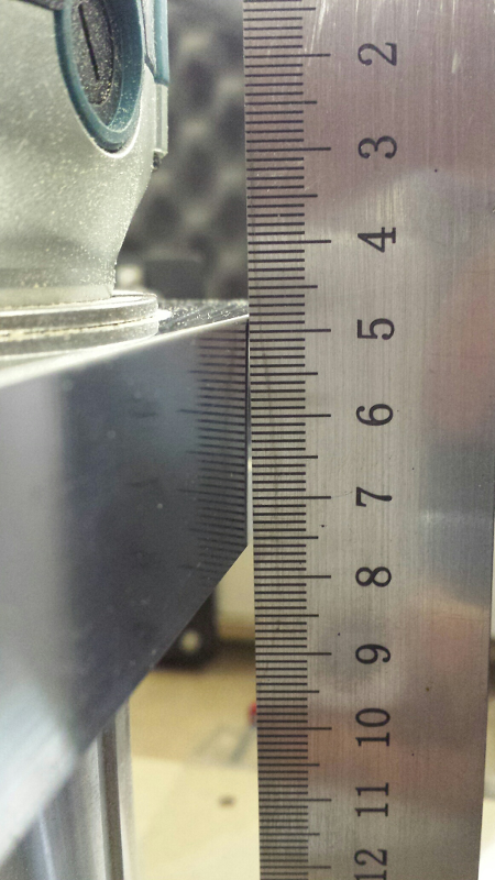
so no correction needed there. On the front/back side though, I did find a non-negligeable tilt angle:
So it seemed like I need to correct this tilt angle. I loosened the 8 screws on the left and right side of the gantry, to get some wiggle room. Then I rotated the gantry a bit in the opposite direction of the tilt angle I noticed, fastened the 8 screws again, and re-checked:
Not perfect, but MUCH better. Since I modified the machine geometry slightly during this adjustement, I re-surfaced the wasteboard to make sure it was parallel to X/Y axis again.
I re-run the initial pocketing job, and sure enough the situation improved significantly: you can still see some stripes, but they are much less visible.
Feeds & Speeds calibration
This great tutorial presents an experimental way to determine the right feeds and speeds for a given material/endmill combination. I definitely want to try that someday, in addition to the theoretical approach/G-wizarding.
(to be continued)
Router RPM calibration
I initially trusted the Makita manual about the RPM I would get when turning the speed dial to a given index, but felt the need to verify the actual RPM I was getting, and more importantly how exactly to place the dial, since there is no marking on the router body, and one can only guess that the index should be aligned “somewhere in the middle”. So I went crazy and spent 12 euros on a tachometer to check this.
The tachometer is just a glorified laser pointer, that measures reflected light off a rotating object, and counts the number of light intensity transitions per second. So the help this process, a piece of white tape must be placed on the rotating part, and the laser aimed at it.
I used a small piece of the reflective white tape that came with the tachometer, and placed it on the nut of the router:
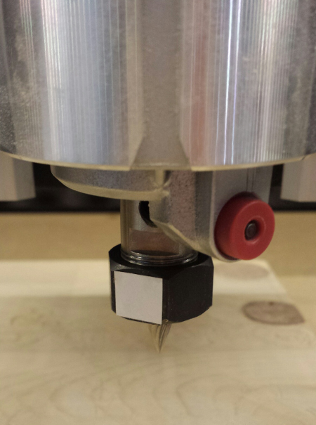
Then turned on the router, and tweaked the dial position to get as close to 12000 RPM as possible (since this is the RPM I use most often, it makes sense to use it as the reference point for my calibration):
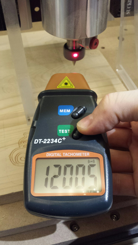
And finally marked the exact associated position of the “2” index on the dial on the router body:
Interestingly, the mark is not exactly in the middle, so it was worth checking, and the mark gives a useful visual indication to tune the dial in any case. I know that a 5-10% error in the RPM is not going to affect the chipload that much, but when experimenting with feeds and speeds I might as well get the RPM I am asking for, not 10% less or 10% more.
Moving the dial indexes aligned to this calibrated mark, I measured:
- 1 => 9546 RPM (manual says 10000)
- 2 => 11998 RPM (manual says 12000)
- 3 => 16880 RPM (manual says 17000)
- 4 => 21900 RPM (manual says 22000)
- 5 => 26600 RPM (manual says 27000)
- 6 => 29949 RPM (manual says 30000)
Abusing Carbide Create
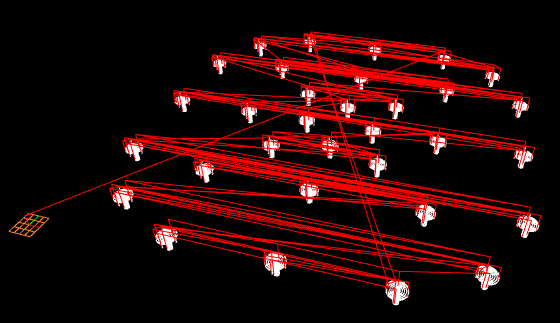
After I found out that Carbide Create uses cleartext JSON formatting to store shapes & toolpaths, I wanted to see how hard it would be to generate some projects, for cases that would be very tedious to do manually. A couple of hours of Python coding later, I had a script generating a 16x16 waveform and associated toolpaths:

which looked nice in simulation:
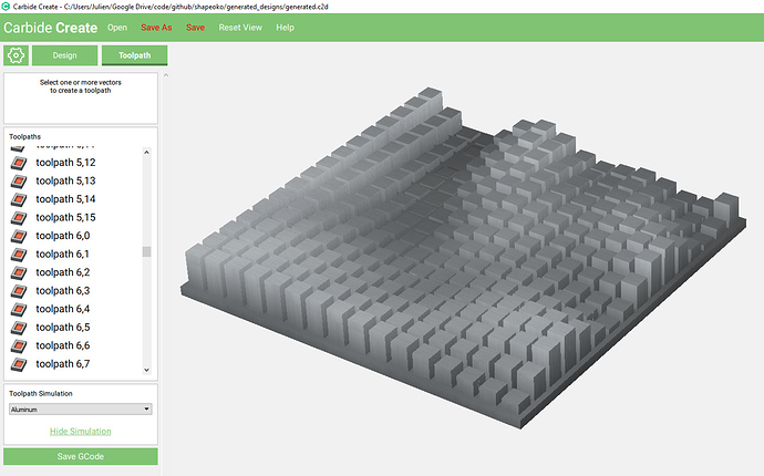
but would take 2hours+ to cut, so I did not bother trying it. Proof of concept for future use of generated CC projects: check.
I increased grid size, just to see when CC would stop taking the abuse, and the max size I could successfully load was 48x48:
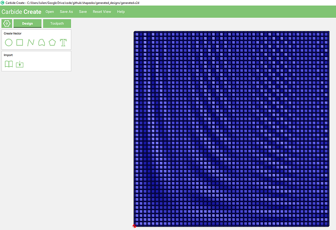
That’s 2300+ shapes, and their 2300+ associated toolpaths, so CC is unexpectedly robust I would say
The Python script is available here
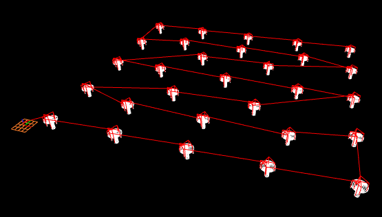
For the sake of actually making something based on this experiment, I generated a 9x9 pattern based on a bell-curve:
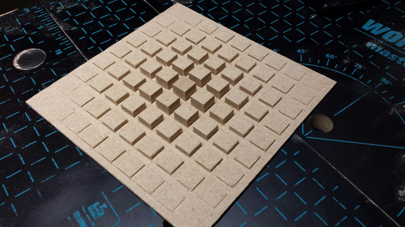
The python script for this is here, and the generated CC project file is here.
Maintenance
Even when using a dust shoe, some amount of fine dust ends up going everywhere on the machine over time. It’s not a problem, until it accumulates beyond a certain level, and may cause subtle imprecisions in the gantry movements for example.
Here is a snapshot of one of the wheels after using the machine intermittently for a couple of weeks, despite using a dust shoe and manually vaccuuming after jobs:
No big deal, but I prefer to keep things tidy, so I try to clean-up around wheels & belts every few weeks using Q-tips and/or a toothbrush. We’ll see if I can sustain that discipline on the long run…or maybe stop worrying about it.
Misc notes
- Makita Carbon brushes replacement parts reference is CB-411. I ordered a couple of those, since sooner or later they need to be replaced and I’ll be glad I have them on hand.
- Instructions page to update to GRBL1.1 & CarbideMotion 4 is here
- Cleaning endmills: I use acetone, which removes any remains of plastic/glue/sticky things very efficiently.
Lessons learned (so far)
- the Shapeoko3 is a GREAT machine. I’m already pleased with its performance, and my machine is not even properly calibrated yet.
- I can already see myself being sucked into the rabbit hole of CNC, this stuff is addictive and there is so much to learn.
- CNC is not a cheap hobby. The Shapeoko is quite affordable and worth every penny, yet with all required accessories the entry cost is somewhere around in the 1500-2000 euros range.
- I read somewhere the motto “measure twice, cut once”. I would say “measure twice, then recheck everything one additional time, and then cut, while keeping your hand on the power switch”. There are many opportunities for getting something wrong.
- Carbide3D’s support has been excellent. It’s a small company, and getting to interact directly with the designers is a huge benefit. My initial controller reset issue was fixed remotely in a few days, and when I later had an unfortunate failure of a stepper driver, they shipped a replacement board immediately.
- Carbide3D’s online community has been very helpful too. A lot of expertise/information from CNC veterans can be gathered there.
- The Shapeoko wiki also has lots of interesting information, though at the beginning there is just too much to swallow for a beginner. By the way, in case any of my fellow French citizens are interested, I translated Shapeoko wiki’s glossary: Shapeoko English/French glossary