Voice Controlled Radio
This project aimed at experimenting with voice control on Raspberry Pi, to command an FM radio module.
- Hardware components
- Raspberry pi setup
- Testing the audio playback/recording
- Speech to Text conversion
- Cabling overview
- Preparing the FM radio module
- Setting up I2C on the Raspberry
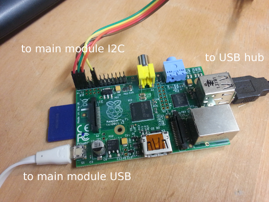
- Connecting the radio module to the Raspi
- Using voice commands to switch radio stations
- Using a push button to trig the voice recording
- Automating the process
- Prototype
Hardware components
Required components are:
- a Raspberry pi
- a USB sound card for the raspberry pi (3$ at DealExtreme)
- a wifi USB dongle (6$ at DealExtreme)
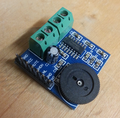
- an audio amplifier module (around 5$ at DealExtreme)
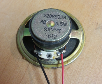
- a couple of speakers
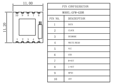
- an FM module with I2C control interface (e.g. TEA5767 FM Radio Module, got 5 of them on eBay for 10$)
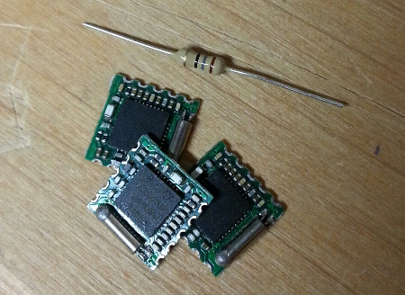 Note: these things are SMALL. Resistor included in the image for scale…
Raspberry pi setup
I installed a default Raspbian distribution from raspberrypi.org
1) transfer raspbian image to SD card:
sudo dd bs=1M if=XXX-raspbian.img of=/dev/xxx
2) plug-in a mouse/keyboard/HDMI display and boot-up
3) Use raspi-config to configure the raspberry as required (e.g. keyboard layout)
4) Plug wi-fi dongle, boot to graphical environment, configure wifi settings.
5) Plug & configure USB sound card (which is required to get sound input, as it is not available on the raspberry board itself). In my case it boiled down to:
sudo nano /etc/modprobe.d/alsa-base.conf
change:
options snd-usb-audio index=-2
into:
options snd-usb-audio index=0
And reboot the pi:
sudo reboot
Testing the audio playback/recording
Test sound output:
speaker-test -c2 -D hw:0,0
(will generate white noise, alternatively on left/right channel)
Test sound input: Plug in a microphone in the USB audio dongle input, then:
arecord -D plughw:0,0 -f cd test.wav
(Ctrl+C to interrupt recording)
Check that recording was correct:
aplay test.wav
Speech to Text conversion
The voice commands will use the google voice online API. This command will record a few seconds of audio, perform the online request, and display the resulting text as it was recognized by google voice service.
arecord -D plughw:0,0 -f cd -t wav -d 3 -r 16000 | flac - -f --best --sample-rate 16000 -o out.flac; wget -O - -o /dev/null --post-file out.flac --header="Content-Type: audio/x-flac; rate=16000" http://www.google.com/speech-api/v1/recognize?lang=fr | sed -e 's/[{}]/''/g'| awk -v k="text" '{n=split($0,a,","); for (i=1; i<=n; i++) print a[i]; exit }' | awk -F: 'NR==3 { print $3; exit }'
NOTES:
- I borrowed this command line somewhere on the raspberry pi forums, can’t remember where exactly.
- this command line is configured for french voice, the language can be changed with the
lang=xxxoption - you might need to install flac:
sudo apt-get install flac
Cabling overview
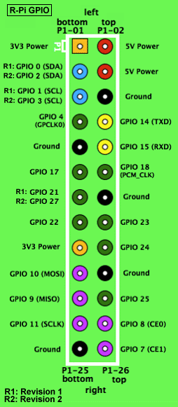
The different elements will be connected as depicted below:
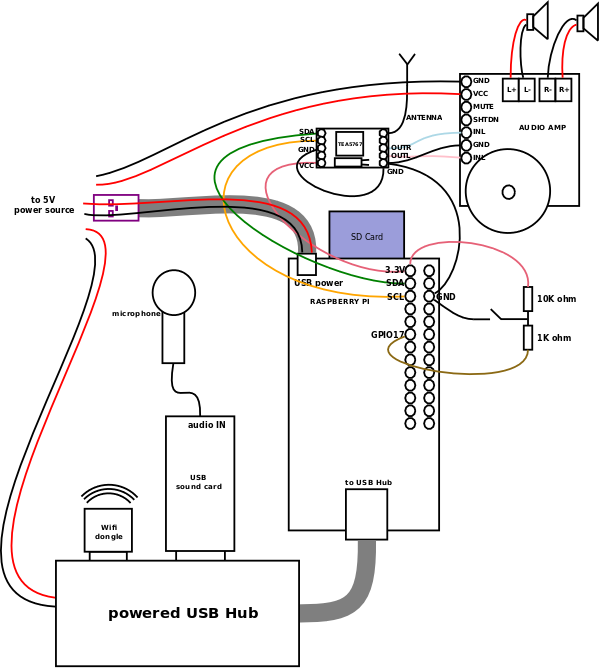
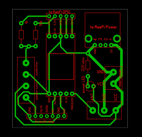
Note that one GPIO input pin (in this case GPIO17, this is arbitrary) will be connected to a push button via a couple of pull resistors. This will allow to trig a specific action (e.g. acquire voice command) on the raspberry when the button is pushed. More on this below.
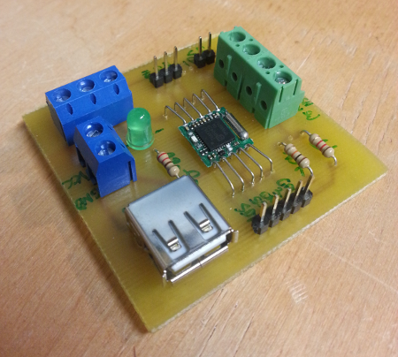
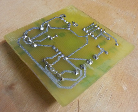
Preparing the FM radio module
The TEA5767 FM radio module itself is very small, and does not have connectors. I created a simple breakout PCB around this module, that also allows to distribute power to the module, the raspberry pi, and the USB hub. Soldering the 6 leads around the tiny FM module requires precision, but is not too difficult.
Setting up I2C on the Raspberry
Instructions for enabling I2C on the raspi are available on this page.
The command ls /dev/i2c* should then show two I2C devices (one is high speed, the other is low speed)
Connecting the radio module to the Raspi
The raspberry will control the radio module through its I2C interface, a.k.a. 2-Wire. Communication happens over two lines:
- SDA: Serial DAta
- SCL: Serial CLock
The radio module should be powered with 3.3V, which the Raspberry GPIO connector conveniently provides on pin 1. SDA and SCL are on pins 3 and 5, and GND can be connected on pin 6.
To test the I2C communication, install the i2c-tools package:
sudo aptitude install i2c-tools
Then scan the bus:
sudo i2cdetect -y 1

     0  1  2  3  4  5  6  7  8  9  a  b  c  d  e  f
00:          -- -- -- -- -- -- -- -- -- -- -- -- --
10: -- -- -- -- -- -- -- -- -- -- -- -- -- -- -- --
20: -- -- -- -- -- -- -- -- -- -- -- -- -- -- -- --
30: -- -- -- -- -- -- -- -- -- -- -- -- -- -- -- --
40: -- -- -- -- -- -- -- -- -- -- -- -- -- -- -- --
50: -- -- -- -- -- -- -- -- -- -- -- -- -- -- -- --
60: 60 -- -- -- -- -- -- -- -- -- -- -- -- -- -- --
70: -- -- -- -- -- -- -- --
The radio module shows up at address 0x60 on the I2C bus. To enable access to /dev/i2C without root permissions:
sudo nano /etc/udev/rules.d/99-i2c.rules
with this content:
SUBSYSTEM==\"i2c-dev\", MODE=\"0666\"
Using voice commands to switch radio stations
Python is a convenient way to quickly send commands to the radio module. I installed a python library to support I2C, as follows:
cd /home/pi
git clone https://github.com/quick2wire/quick2wire-python-api
export QUICK2WIRE_API_HOME=/home/pi/quick2wire-python-api/
export PYTHONPATH=$PYTHONPATH:$QUICK2WIRE_API_HOME
I borrowed the tea5767.py from https://github.com/pcnate/fm-radio-python/, and adapted it a bit so that it takes a radio state name (string) as an input, looks up the corresponding frequency in a local table, and sets this frequency on the radio module through I2C. And voila, the following command will acquire a few seconds of audio input, convert it to text, which in turn will be used by the python script to set the station.
arecord -D plughw:0,0 -f cd -t wav -d 3 -r 16000 | flac - -f --best --sample-rate 16000 -o out.flac; wget -O - -o /dev/null --post-file out.flac --header="Content-Type: audio/x-flac; rate=16000" http://www.google.com/speech-api/v1/recognize?lang=fr | sed -e 's/[{}]/''/g'| awk -v k="text" '{n=split($0,a,","); for (i=1; i<=n; i++) print a[i]; exit }' | awk -F: 'NR==3 { print $3; exit }' | xargs ./tea5767.py
The modified python script (tea5767.py) is available here
Using a push button to trig the voice recording
I used one GPIO pin of the raspberry to get notified when the button is pushed, and trig the voice recording/command. This GPIO pin (GPIO 17 in this case) is normally pulled-up to 3.3V through a ~10k resistor, so it will read a logical “1”. When the button is pushed, the pin is pulled to GND through a 1k resistor hence reads a “0”.
To create a GPIO file access to pin 17:
echo 17 > /sys/class/gpio/export`
To configure the pin as an input:
echo in > /sys/class/gpio/gpio17/direction
To read the pin value:
more /sys/class/gpio/gpio17/value
Automating the process
Now, you might want to write a script that is polling the button state, and launches the voice-controlled FM tuning change whenever the button is pressed. This script can be launched at startup time, and then continuously run in the background.
An example (button_poll.py) is available here
Add a line in /etc/rc.local to launch this script and you are good to go.
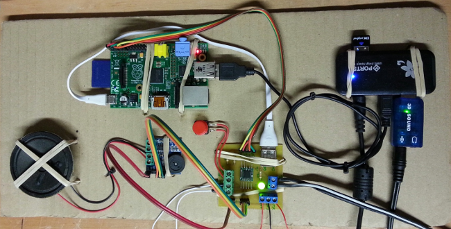
Prototype
Final view of the hackishly assembled system (with only one audio output connected)
And here is a short video: