Homemade Video Surveillance
The aim of this project was to implement a low-power homemade video surveillance system using a cheap IP camera and a raspberry pi. There are several available frameworks/examples to achieve this, but…it is so much more interesting to build one from scratch, right ?. This has already been done numerous times, there is plenty of information over the internet and no real difficulty is involved. That is, if one chooses a decent IP camera, that can be accessed over HTTP as is the case for 99% of them. Unfortunately, I picked a cheap camera that uses a proprietary protocol, for which only a Windows client is available. Sigh…so I ended up spending most of the project time reverse engineering the camera protocol.
- Hardware parts
- Overview
- Raspberry pi setup
- Testing the audio playback
- IP camera setup
- IP camera protocol
- Installing openCV
- Motion detection algorithm
- The surveillance code
- Installing the system
- Misc notes
- Lessons learned
Hardware parts
Anyway, here are the involved components:
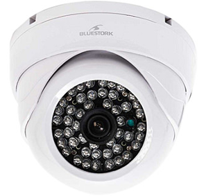
- an IP camera (in this case, a cheap model “InDoorCAM P2P” from Bluestork)
- a Raspberry pi (Model B+, but any model will do)
- a USB stick
- a wifi USB dongle (about 5$ at DealExtreme)
- a USB sound card for the raspberry pi (less than 3$ at DealExtreme)
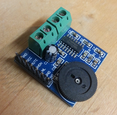
- an audio amplifier module (around 5$ at DealExtreme)
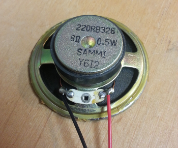
- a speaker
Overview
In this project, the raspberry pi is entirely dedicated to capturing images from the camera and analyzing them. The camera is able to communicate over wifi, but to get maximum reliability, it will be connected to the raspi through an ethernet cable. Independently, a wifi dongle is used to communicate with the home router (e.g. to download images, administrate the system, etc…)
The system is connected as follows:
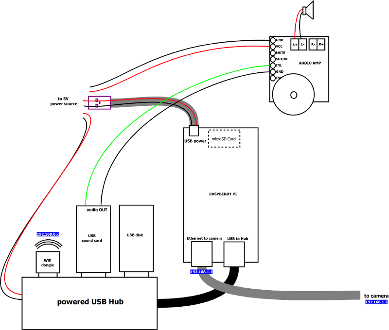
Notes:
- a powered USB hub is used, even though the Raspi model B+ has enough USB ports. This is because I ran into issues when powering a lot of stuff over the raspi’s USB in previous projects, so I don’t even take a chance anymore, an externally powered hub gives a more stable system.
- the use of a USB sound card is overkill here, the audio output of the pi would have been good enough, but I initially wanted to have the capability to record sound too.
- the USB stick will be used (exclusively) to store live images when image detection is triggered.
Raspberry pi setup
I installed a default Raspbian distribution from raspberrypi.org
1) transfer raspbian image to SD card:
sudo dd bs=1M if=XXX-raspbian.img of=/dev/xxx
2) plug-in a mouse/keyboard/HDMI display and boot-up
3) Use raspi-config to configure the raspberry as required (e.g. keyboard layout)
4) Plug wi-fi dongle, boot to graphical environment, configure wifi settings.
5) Plug & configure USB sound card (which is required to get sound input, as it is not available on the raspberry board itself). In my case it boiled down to:
sudo nano /etc/modprobe.d/alsa-base.conf
change:
options snd-usb-audio index=-2
into:
options snd-usb-audio index=0
6) Surprisingly, I had a hard time setting up the network config to have both wifi and ethernet simultaneously working. By default, whenever I plugged an ethernet cable, the wifi interface would be shut down. The following changes were required to achieve the desired setup:
Edit /etc/network/interfaces
auto lo
iface lo inet loopback
auto eth0
allow-hotplug eth0
iface eth0 inet static
address 192.168.1.1
netmask 255.255.255.0

auto wlan0
allow-hotplug wlan0
iface wlan0 inet manual
wpa-roam /etc/wpa_supplicant/wpa_supplicant.conf
iface default inet dhcp
Check the content of /etc/default/ifplugd
INTERFACES="auto"
HOTPLUG_INTERFACES="all"
ARGS="-q -f -u0 -d10 -w -I"
SUSPEND_ACTION="stop"
Edit /etc/rc.local to add:
# Disable the ifplugd eth0
sudo ifplugd eth0 --kill
sudo ifup wlan0
7) Prepare mount point for USB disk
sudo mkdir /mnt/imagestore
sudo chmod a+w imagestore
8) Setup auto-mount of USB disk at boot time, adding in /etc/fstab:
/dev/sda1 /mnt/imagestore ext4 defaults 0 0
Finally reboot the pi:
sudo reboot
Testing the audio playback
Checking sound output :
aplay <any wav file>
IP camera setup
I proceeded as follows to configure the IP of the Bluestork camera:
- connect to the camera over wifi, using the provided Windows client
- In the “LAN” tab, right-click the camera to adjust IP address (192.168.1.2 in my case)
Note : since my local wifi network is 192.168.0.xxxx, after this setup, the camera cannot be accessed directly over wifi anymore.
This camera delivers 640x480 images, at up to (theoretically) 30 images per second, but I configured it to send 3 images/sec, which is enough for my need (and ensures that my image analysis code keeps up easily)
An interesting tip: by default the camera comes with a Telnet server installed, and the login/passwd is “admin/admin” (sigh…) This revealed a few interesting things, like the UDP ports the camera is using:
	~ # netstat -l
	Active Internet connections (only servers)
	Proto Recv-Q Send-Q Local Address           Foreign Address         State
	tcp        0      0 :::23                   :::*                    LISTEN
	udp        0      0 0.0.0.0:5000            0.0.0.0:*
	udp        0      0 0.0.0.0:2473            0.0.0.0:*
	udp        0      0 0.0.0.0:2627            0.0.0.0:*
	udp        0      0 0.0.0.0:11760           0.0.0.0:*
	udp        0      0 0.0.0.0:8694            0.0.0.0:*
	Active UNIX domain sockets (only servers)
	Proto RefCnt Flags       Type       State         I-Node Path

	/bin # cat /proc/cpuinfo
	system type             : Ralink SoC
	processor               : 0
	cpu model               : MIPS 24K V4.12
	BogoMIPS                : 239.61
	wait instruction        : yes
	microsecond timers      : yes
	tlb_entries             : 32
	extra interrupt vector  : yes
	hardware watchpoint     : yes
	ASEs implemented        : mips16 dsp
	VCED exceptions         : not available
	VCEI exceptions         : not available
User config files happen to be stored in /mnt/spinand/sif, and specifically:
/mnt/spinand/sif # cat hkclient.conf
wifiopen=0
USER=<redacted>
LANPORT=5000
PORT=8080
Alias=IPCAM
VERSION=41
UpdateUrl=http://www.uipcam.com/app/experience/download.jsp?fileName=bsd_6360.txt
WANENABLE=0
PROXY=bluestork.scc21.net
LogLevel=0
PASSWD=n4qpj7
LogBackground=1
CLIENT=hkipcame
/mnt/spinand/sif # http://www.uipcam.com/app/experience/download.jsp?fileName=bsd_6360.txtCommitRemoteHostInfo   1
CommitRemoteHostInfo   2
CommitRemoteHostInfo   1
CommitRemoteHostInfo   2
IP camera protocol
The IP camera model I chose unfortunately does not support standard (e.g. HTTP) communication to retrieve images, but uses a proprietary protocol based on UDP, implemented by a Windows client. So I ended up reverse engineering just enough of the protocol to be able to start the image acquisition and get the image data. Using the Windows client with Wireshark running in the background, and after countless hours of head scratching and trial&error tests, I isolated a packet sequence fulfilling my need (though most of the details of the protocol remain obscure, at least I got the d***** thing to work). The sequence goes as follows:
* Initialization sequence:
  * initialize an UDP socket, bind it to any available port on the local pc
  * All UDP packets mentioned below will be sent to the camera's IP address on port 5000
  * send 43 bytes (constant data as retrieved from Wireshark logs)
  * send 13 bytes (template data as retrieved from Wireshark logs + random value in 7th byte)
    * receive 13 bytes in return
    * the 5th byte should have its bit4 set, and the 7th byte should not have had its bit6 set
    * if this is not the case, retry until this is the case
  * send another 13 bytes (constant data as retrieved from Wireshark logs)
  * send another 13 bytes (constant data as retrieved from Wireshark logs)
    * get 13 bytes in return
  * send 212 bytes (constant data as retrieved from Wireshark logs)
    * receive 155 bytes in return
  * send 34 bytes
  * send 119 bytes
    * receive 368 bytes in return
* At this point the image data packet will start coming
* The first image data packet has a 15 bytes header, followed by the JPEG StartOfImage pattern (0xffd8)
* subsequent packets have a 4 bytes header, the first byte being a simple sequence number incremented at each packet
* one of the subsequent packets will have an EndOfImage pattern (0xffd9) in its data, which completes the reception of one frame.
* NOTE: after a	few images, the end of image pattern does not necessarily come as the last two bytes of a fragment, but can be in the middle of a packet, immediately followed by the beginning of the data for the next frame.
* to sustain the image flow, every few packets received, a control packet needs to be sent, with most of the data taken from wireshark capture, and the last bytes updated dynamically, based on a predefined sequence (0xd9,0xd8,0xdb,0xda,0xdd,0xdc,0xdf,0xde,0xd1,0xd0) and subtle variations over time. Check the code for details, this part was tricky)
Side note:
Rik Bobbaers pointed out an interesting lead to go further in this reverse engineering exercise: the MrSafe HD Indoor camera is apparently similar to the Bluestork model I own, and comes with an Android app (get it here) that could maybe be reverse-engineered, more easily than the Bluestork windows app:
- unzip the apk and get the
classes.dexfile, which can be unpacked with dex2jar:
./d2j-dex2jar classes.dex-
a Java decompiler like this one could then be used to help figuring out the protocol: launch
JD-GUI, open theclasses.dexfile, and there you go, the java classes source code. -
In addition, apktool can be used to extract info from the original apk file, especially to get the unencrypted content of all XML files
apktool d mrsafe-0522.apkIn directory /x1/Studio/Ali, Start.java and Video.java look interesting. Mentions of devices supporting P2P protocol in the code is also a hint (though I already tried some generic P2P client to connect to my camera, and failed). This reverse engineering effort is to be continued for now…just for fun, since the current code is good enough anyway to get everything working as far as I am concerned.
Installing openCV
I will be using openCV for implementing the image analysis. To install it on the raspberry pi, first check the raspi repo database is up to date :
sudo apt-get update
Then just install openCV:
sudo apt-get install libopencv-dev python-opencv
ffmpeg is required to save images as compressed video:
sudo apt-get install ffmpeg
Motion detection algorithm
A very simple differential images algorithm is used, to keep performance requirements to a minimum.
- at all times, keep the latest two captured images (N-2 and N-1) in memory
- capture a new image (N)
- convert it to grayscale
- compute the absolute difference (in grayscale) between N and N-2, and between N and N-1.
- compute the bitwise AND of these two delta images
- apply a threshold on the resulting image to get a binary result (pixel below threshold at 0, pixels above threshold at 255)
- count the number of pixels at 255.
- a detection is notified if this number exceeds a predefined threshold.
Then it is all a matter of carefully choosing the various settings/threshold to minimize false positive while keep a decent sensitivity. Experimentation is key, since it depends a lot on the type of scene being captured.
The surveillance code
An easy way to start experimenting with image capture early during the project was to use a python script to send/receive packets. I initially planned to move to a C implementation later now for performance concerns, but it turns out that for my limited need (capturing/analysing/saving a few low-res images per second), Python running on the raspi is just fine performance-wise.
The script therefore ended up doing this:
- send the magic packets previously identified to start image flow
- loop (until a socket error occurs) doing this:
- read incoming packets
- accumulate enough packets to have (probably) enough data for a whole image
- if enough data is available, search the data for the jpeg “start of image” and “end of image” markers
- if the markers are found, isolate the JPEG data bytes, and start image analysis:
- read the data as an openCV image
- apply the image analysis described above. If motion is detected:
- in this case, save the N-2, N-1, and N images, and trig the capture of the next few images too.
- also play a beep sound on the audio output upon detection.
- in any case, shift the N-2/N-1/N images for next iteration.
- every few fragments received, compute and send the “continue” packet, as per the reverse-engineering protocol.
- if the markers are found, isolate the JPEG data bytes, and start image analysis:
- if a socket error occurs (cheap camera…), restart at the beginning.
As an example, it captured a random cat passing by:
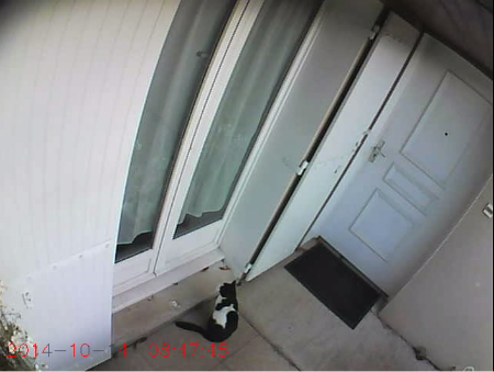
And the associated binary image that triggered this particular capture:

Note: After a while, I noticed that some of the detections were triggered by the plant in the lower left corner, whenever it was slightly moving with the wind. To avoid this, I added a mask in the motion detection algorithm, with this part of the image masked out. The mask is as follows:

Note that due to the specific image orientation of my setup, the mask image is flipped horizontally and vertically.
Video files management
The script also:
- opens a new capture file everyday, in which all motion detections for that day will be concatenated. This allows to quickly review the surveillance images for a given day by opening a single file
- dumps the binary image corresponding to each detection, for debug purposes.
- unconditionnally dumps a single image every 15 minutes, as a background monitoring
A cron rule is in charge of cleaning up old capture files, deleting the oldest ones (older than 4 days in this example):
0 0 * * * date \&\& find /mnt/imagestore -mtime +4 -exec rm -rf {} \; >> /mnt/imagestore/purge.log 2>\&1
Source code
The full python script is available here. Note that the hardcoded byte sequences apply to my camera, you would have to capture your own data with Wireshark. This is horrible python code, it started as a simple hack to play with camera settings, and ended up being the base for the final version since I got fed up after finally completing the reverse engineering part, and did not have the courage to clean it up.
Installing the system
The final installation in its weather-proof box is show below. The top cover of the box contains the USB hub, the USB storage, the audio, and the wi-fi dongle:
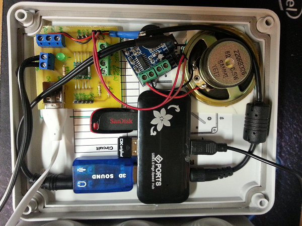
Note : the small PCB with screw connectors contains a chip that is unused in this project, I just happened to reuse this PCB from another project for convenience purposes (see here)
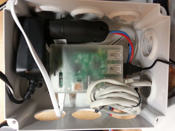
The other side of the box contains the Raspberry pi and the main power supply:
Misc notes
Logging
When executing the python script as a background job and redirecting its execution output to a logfile, I noticed that none of the print statements seemed to end up in the log file. It turns out that by default, python buffers the outputs and they might not end up in the log before a while. To ensure that all outputs appear in the log file as soon as they come, I used the -u (unbuffered) python option. The complete line to start the script in the background while also capturing its output is:
python -u surveillance.py > surveillance.log 2>&1 &
Camera viewing angle
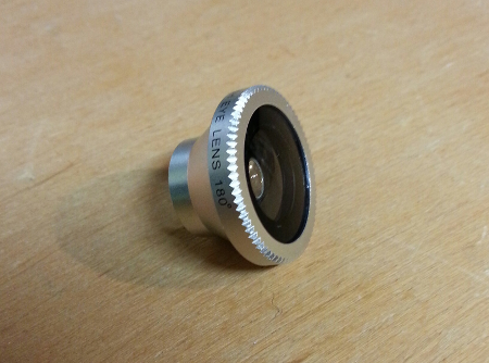
The IP camera I bought has a limited viewing angle. Since it is mounted quite near the front door, I was not able to view everything I needed. I just bought a super cheap chinese wide-angle lens for smartphones (a few dollars), and considering that I don’t care about image quality, this did the job.
Security disclaimer
There is no security management whatsoever. The reason is simple: the camera only captures images of my front door, which is visible from the street anyway. I just don’t care about the camera being hacked. I would NEVER deploy such an unprotected system for an indoor camera, where very strong privacy/security concerns apply.
Remote image storage
After a while, I decided to store images remotely (on a NAS) instead of locally on the USB stick, for two reasons:
- I had two problems 6 months apart where somehow the file system on the USB stick got corrupted. In retrospect, using a USB stick as a permanent image storage media is not a very wise decision.
- it’s safer this way, the images now being stored directly inside the house, I will still have access to them if something bad (…) happens to the outdoor camera box.
Anyway, I changed one line in etc/fstab to mount a NAS shared folder over NFS, instead of the USB stick:
192.168.0.12:/volume1/backup/videosurveillance /mnt/imagestore nfs defaults,user,auto,noatime 0 0
Lessons learned
- OpenCV is AWESOME and even simpler to use than I anticipated, especially in Python.
- Python is good enough for (slow) real-time image analysis, even on a raspi.
- Properly filtering out false positives in image motion detection algorithm is tricky.