BlueKey, a bluetooth hardware password manager
- Overview
- Security Disclaimer
- PROTOTYPE #1 (Breadboard)
- PROTOTYPE #2 (More breadboard)
- An unexpected detour in low-memory land
- Bluetooth auto-connect
- Off-topic: receiving data from the RN42
- PROTOTYPE #3: the SNES variant
- PROTOTYPE #4: the NES variant
- Using the BlueKey
- Display orientation
- Display performance
- Todo list
- Source Code
- Afterthoughts
- Lessons learned
Overview
I have been thinking about improving my password management routine, and looking at existing password managers. My main requirements were that it should:
- be usable from all platforms I use (Windows, Linux, Android)
- be reasonably secure (for moderately critical login/passwords, since I will still memorize my most critical passwords and/or use SMS-based two-factor authentication when available)
- NOT involve cloud-based key storage, or any internet connection for that matter
- be low-cost
As far as I can tell there are basically two main approaches:
- Software-based password vaults: many free and paid versions exist, but call me paranoid, I won’t blindly trust a huge pile of closed-source SW connecting to the internet (as most commercial password managers do to support synchronization over supported platforms) with my passwords.
- Hardware devices (e.g. USB key/dongles), mostly used for supporting two-factor authentication. These are great, but until every single site/service I need to log into supports 2FA and whatever keyfob I would buy, then this is not practical enough.
I was leaning on the hardware side when I stumbled on this project: The FinalKey
This little DIY hardware password manager is an arduino with an EEPROM, in a 3D-printed case, that allows to store encrypted passwords, and then pretends to be a USB keyboard to type in passwords for you, after selecting the account to be accessed from a neat little SW client on the computer, and pushing the button on the device (as a security measure).
This thing is absolutely AWESOME, super low cost, and open source, and matches pretty much all of my requirements. Hats off to Jimmy for creating this. I immediately felt a DIY itch that needed scratching. So I decided to roll my custom version of a FinalKey, with some modifications to better suit my needs. Mostly, the one usecase that is not covered by the original FinalKey is usability with a smartphone: plugging a USB cable to use the FinalKey is not very convenient on a phone, and I would have had to develop an Android version of the FinalKey client software too.
So I took a slightly different approach:
- I wanted the master key to be input on the device itself, not from the computer/phone connected to it (call it paranoia again), so this meant:
- adding controls on the device for the user to type in the master key/code
- and therefore adding a display on the device
- to remove the need for connecting a USB cable, I added a Bluetooth module supporting HID profile, which means the device presents itself to any nearby Bluetooth-enabled computer/phone as a bluetooth keyboard
- I wanted to be able to use the device with no specific software installed on the target computer/phone:
- as the device emulates a standard Bluetooth keyboard, no specific SW is required to receive characters over the wireless link
- I intentionnally gave up the functionality of being able to update the internal password database from the host computer, and instead only kept the original FinalKey’s capability to generate new passwords, store them internally and send them out.
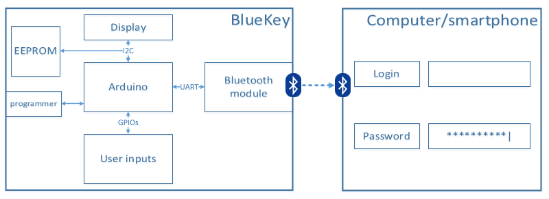
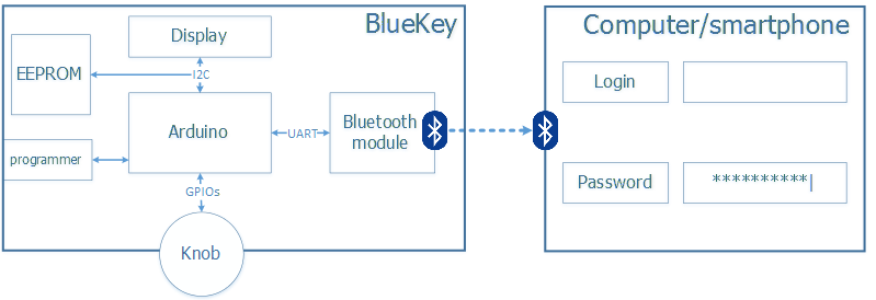
Hence the BlueKey concept:
Security Disclaimer
The original FinalKey code has a very decent security level, effort has been put into securing it, and it documents its few limitations quite openly. My version on the other hand is heavily modified and I am not even trying to claim that it reaches a similar level of security, especially considering it is wireless. It is what it is (mostly a fun experiment) and I am not trusting it enough to handle my “serious” passwords, so you shouldn’t either.
PROTOTYPE #1 (Breadboard)
Hardware
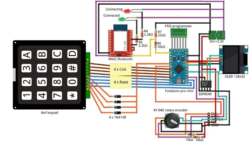
Below is a description of the parts I used for the first prototype.
Arduino board
I used a Funduino Pro Mini 5V/16MHz (but pretty much any arduino could be used) => about 5$
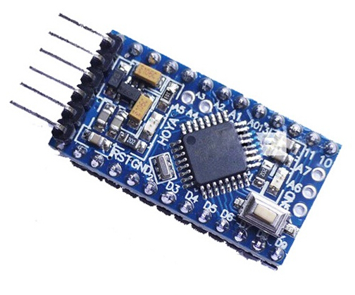
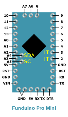
- GND/5V/RX/TX/DTR at the bottom can be connected to a USB programmer to upload sketches in the arduino
- RX and TX are connected to the bluetooth module’s UART
- pin2 and pin3 are used for interrupts
- A4 and A5 are used for I2C communication with the display and EEPROM
- GPIOs 4,5,6,7,8,9,10,11 are used to scan the keypad matrix
- GPIO 12 is used for reading direction of the rotary encoder
- GPIO A0 is used for reading switch status of the rotary encoder
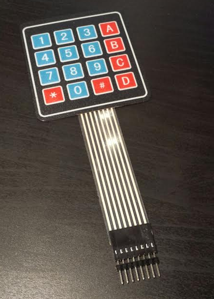
Keypad
4x4 matrix keypad, 4$ on ebay. The keypad is HUGE compared to the other parts, but I could not find any smaller (while equally cheap) ones
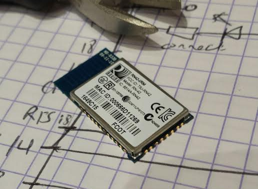
Bluetooth module
I bought this RN42 module with HID profile (this is important) for about 25$. This is by far the most costly part of the list. There are a lot of much cheaper (HC-05/06) bluetooth modules, but they usually do not come with a firmware supporting HID profile. Yes, there are ways to get the firmware from an RN42 and install it on a cheapo HC-0x module, but this is not legal and the time I spared buying an actual RN42 module is well worth the 25 bucks anyway. Be aware that this thing is SMALL, soldering leads to it was not a piece of cake.
The module has the following pinout:
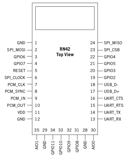
- pin1 is connected to GND
- pin11 is connected to the regulated 3.3V power supply
- pin12 is connected to GND
- pin13 (UART_RX) is connected to a the TX pin of the funduino through a simple voltage divider (to drop the arduino’s 5V TX level to around 3V)
- pin14 (UART_TX) is connected to the RX pin of the funduino
- pin15 (UART_RTS) and pin16 (UART_CTS) are connected together since no HW flow control is required
- pin 19 (GPIO2) is connected to an LED (with 2k ohm resistor in series) to show the status of connection (LED OFF when connected)
- pin 21 (GPIO5) is connected to an LED (with 2k ohm resistor in series) to show the status of connection (blinking when waiting for connection)
EEPROM
24LC512 with I2C interface, got 4 for 10$
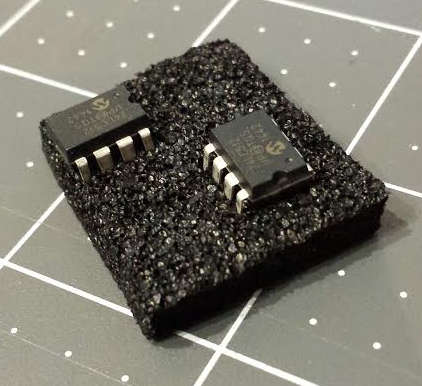
The pinout is as follows:
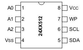
- A0/A1/A2 are connected to GND (this sets the I2C address)
- VSS (GND) is connected to the GND
- VCC is connected to the Funduino’s 5V rail which is ok since the component can take anywhere between 2.5V and 5.5V
- WP (Write Protect) is connected to GND, I don’t need this feature for now.
- SDA and SCL (the I2C interface) are connected to the funduino’s I2C bus.
OLED display
I picked the cheapest module I found, a 128x32 pixels display with I2C interface, for about 10$. It is quite tiny, but suits my usecase, I only need a few lines of text to be displayed and read at arms’ length.
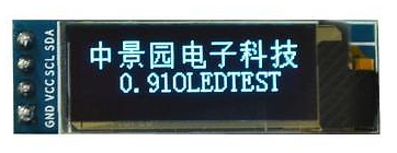
- VCC is connected to the funduino’s 5V rail, which is ok since the component accepts a Vcc range of 2.8V to 5.5V
- GND is connected to the circuit’s GND
- SDA and SCL are connected to the funduino’s I2C bus (this is the beauty of I2C, there is no issue to have both the EEPROM and display on the same I2C interface, their specific address will be used to speak to one or the other)
Rotary encoder
I happened to use a KY-040 module, bought for 2$ on ebay. This is used as the main user interface to scroll through text lines in this prototype. It includes a switch (activated by pushing on the shaft itself).
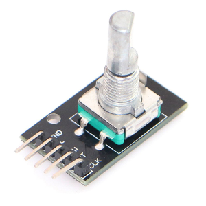
- CLK is the main signal that will be pulsed when the shaft is turned
- DATA is the secondary signal that will be used to determine rotation direction
- SW is the signal for the switch embedded in the encoder shaft
- + is connected to the funduino’s 5V
- GND is connected to the circuit’s GND
Other stuff
- 5V to 3.3V converter (about 2$). This is only necessary because I used a 5V arduino model, while the RN42 module requires 3.3V power supply.
- 4 x 1N4148 diodes (~0$). These are used in the keypad readout mechanism.
- two LEDs (~0$). They are used to show the current state of the RN42 module (connecting/connected status)
- a few resistors (~0$)
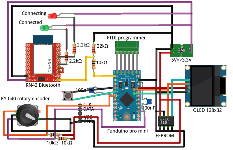
Breadboard assembly
The setup is as follows:
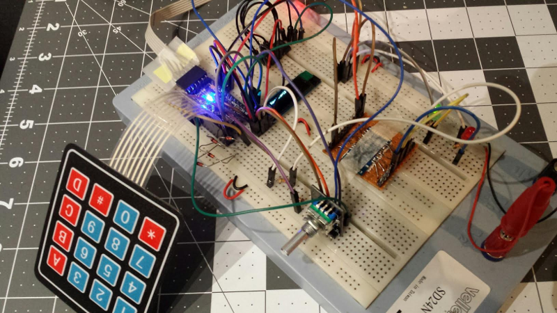
And here is the messy breadboard result:
Software
RN42 bluetooth module configuration
By default, the module is configured for SPP (Serial Port Profile) and for communicating over its UART interface at 115200 bauds. Once wired as described above and powered, it should show up as an available bluetooth device in any nearby bluetooth-enabled phone (or computer).
To verify proper operation of the module, I:
- set the Serial bitrate to 115200 in the arduino code (instead of the typical 9600 value)
- used the
BlueTermapplication for Android - sent a message from the arduino to the module, using a simple
Serial.print - and saw the message showing up in the BlueTerm window. So far so good.
Now, what I really needed was to use the HID (Human Interface Device) profile of the module, so that the module presents itself as a wireless keyboard. To do this, from either the local serial link or over the wireless serial terminal (e.g. BlueTerm), type in the following commands
$$$
This switches the module in COMMAND mode, and the device answers CMD. Then type:
S~,6
and hit enter: this enables HID profile, and the device answers with AOK
Then type
R,1
and hit enter: the device answers Reboot! and… reboots.
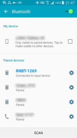
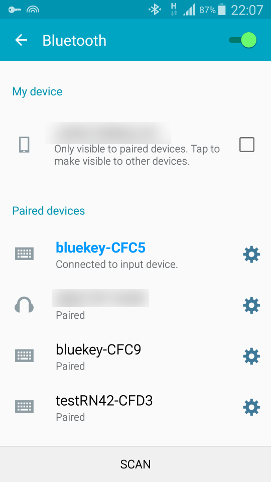
I then un-paired the device, relaunched a bluetooth scan, re-associated the device, and sure enough it now showed as a keyboard/input device on the phone:
Once the device is paired like that, it will receive any string sent from the code over the serial line (e.g. Serial.print statement).
Note:
- I archived the User Guide of the RN42 module here, see chapter 5 about support for the HID profile.
- Depending on the module configuration, remote configuration over Bluetooth may not be possible. In this case the best way is to using a local serial terminal, the simplest setup I found is using a 3.3V FTDI adapter (e.g. normally used for programming 3.3V arduinos), connect VCC to RN42’s pin 11 (VDD), connect GND to RN42’s pin 12 (GND), connect RX pin to the RN42’s pin 14 (TX), and TX pin to the RN42’s pin 13 (RX), then launch a serial terminal (e.g. minicom/putty) with baudrate 115200, 8N1, no HW flow control.
Keypad management
The matrix keypad if basically just a set of wires organized in 4 rows and 4 columns, which come in electrical contact under the key that is pushed. The 8 wires are connected to 8 GPIOs on the arduino, and then some code is required to scan the continuity between the rows and columns and figure out if a key was pushed (and which one).
There are existing arduino libraries to manage keypads, but most of those I found rely on polling of row/column lines at regular intervals from the main loop, and I wanted to avoid this (since there is then a strong dependency between the reactivity of the keypad and the main loop execution time, which tends to change over time as code is added). A better option in my opinion is to use interrupts to only execute code when a key is pushed.
Based on the example from this Atmel keypad application note, I therefore wired the keypad as follows:
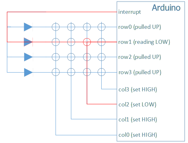
- Row lines are connected to arduino GPIOs that are configured as inputs with pull-ups.
- Column lines are connected to arduino GPIOs that are configured as outputs initially set to LOW/GND state
- All rows are connected to one arduino GPIO that is configured as an interrupt pin (on the arduino model I use, only pins 2 & 3 have this capability), configured as with a pull-up, and triggered upon FALLING edges of the signal.
- the diodes are there to avoid conflicts between multiple rows, they implement a kind of OR operation into the interrupt pin.
- when any key is pushed, the corresponding row is then connected to GND via the column that the key belongs to.
- this pulls the interrupt line LOW, which triggers an interrupt
- the interrupt service routine then scans the rows & columns to determine the pushed key:
- it resets all columns lines to HIGH state
- it then loops through columns, setting them to LOW/GND one by one, and loops through reading all row values for each column : only the column/row combination corresponding to the pushed key will read a “LOW” state.
- it then resets all columns lines to LOW/GND state for next time
This does not take care of multiple simultaneous key push, but for my usecase this is no big deal.
Note: playing with the columns output states within the interrupt service routine could theoretically trig a nested interrupt, and things would get ugly quickly. Fortunately, the arduino (this model at least) implicitly disables interrupts when entering an ISR, and re-enables them automatically upon exiting the ISR.
Display management
The OLED display I used is based on the SSD1306 component, and is interfaced over I2C. Executing the I2C scanner sketch revealed that its address happens to be 0x3c.
I downloaded and installed two great libraries from Adafruit that happen to support this display:
Adafruit_SSD1306 and Adafruit-GFX-Library
(modern arduino IDE can import libraries, for older ones just copy & paste the library folder into the /libraries folder of the arduino IDE, and restart. The only catch is that the library folder name MUST match the library sketch file name)
An example sketch ssd1306_128x32_i2c.ino is available in AdafruitSSD1306 library, and I did not even have to adjust the I2C address of the display, it worked out of the box.
I don’t need all the fancy graphics routine, the print function is all I needed to start with.
EEPROM access
I reused the EEPROM read/write code from the I2Ceep of the FinalKey project, which is available here.
It boils down to the following sequence:
- For each chunk of 32 bytes:
- initialize I2C communication to address 0x50
- write MSB and LSB of target address to be read (or written)
- for write, send the data to be written byte by byte, and end I2C communication
- for read, end I2C communication, request and read incoming data
- wait a few ms before looping to read/write next chunk
Note: the original FinalKey code I used at the time contained a value of 4ms for the delay, which turned out to produce write errors for consecutive writes with the EEPROM I was using. I increased the delay to 8ms and it works fine. Newer FinalKey versions of the code have this increased delay too.
Rotary encoder management
The CLK signal of the rotary encoder is connected to interrupt pin #3 of the arduino, which is configured to trig an interrupt whenever it sees a FALLING edge of the signal.
The DATA pulse will begin either before of after CLK pulse, depending on the direction of the shaft rotation.
So the interrupt service routine checks the current state of the DATA signal at the time it is called, and increments or decrements a counter accordingly.
PROTOTYPE #2 (More breadboard)
On further thought, the keypad did not look practical enough, so I got rid of it and decided to use the knob as the single way to manage user input.
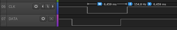
Better rotary encoder management
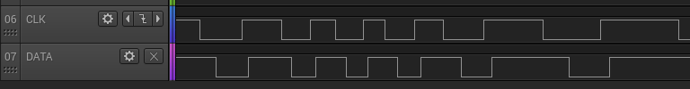
While turning the knob, sometimes the counter registered two increments, while only turning by one step. Zooming way in on the CLK signal falling edge reveals multiple short glitches:
This results in the interrupt routine being called multiple times, and therefore wrongly incrementing the count multiple times on a single step turn.
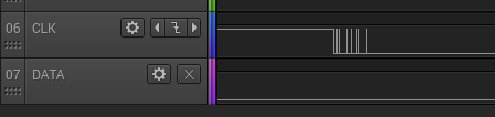
Just plugging a 100nF capacitor be between CLK and GND, and another one between DATA and GND allows to filter out the glitches, and get a nice and clean timeline:
Finally, a basic timing check is included in the ISR to reject calls that happen less than 10ms after the previous one (as inspired by this guy’s page).
Updated breadboard assembly
An unexpected detour in low-memory land
Everything was going fine until I started adding significant amounts of code, when after a while the arduino started misbehaving seemingly randomly. It smelled like memory-related issues, yet the memory status reported by the compiler was nowhere near the limits:
Sketch uses 21650 bytes (70%) of program storage space. Maximum is 30720 bytes.
Global variables use 1576 bytes (76%) of dynamic memory, leaving 472 bytes for local variables. Maximum is 2048 bytes.
How could I encounter problems with 472 bytes of free SRAM left ?
Where did my SRAM go ?
SRAM is mapped as follows on this arduino model:
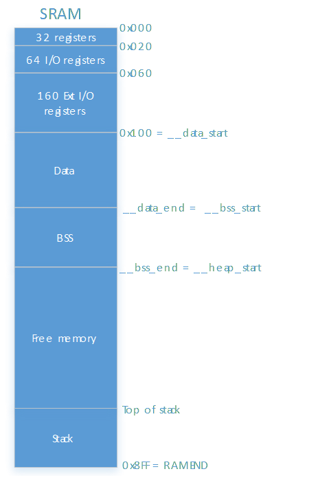
Quick check of the executable with avr-size tool:
etabli@bids-etabli:~/arduino-1.8.1/hardware/tools/avr/bin$ ./avr-size /tmp/arduino_build_525269/BlueKeyFat.ino.elf
   text    data     bss     dec     hex filename
  20834     816     760   22410    578a /tmp/arduino_build_525269/BlueKeyFat.ino.elf
So, 816 bytes of initialized data, and 760 bytes of uninitialized data. I used the avr-nm to check the detailed list of these data:
./avr-nm -Crtd --size-sort /tmp/arduino_build_807388/BlueKey.ino.elf | grep -i ' [dbv] '
Which returned:
00000512 D _ZL6buffer.lto_priv.70
00000242 B ES
00000157 B Serial
00000046 B display
00000034 B TwoWire::txBuffer
00000034 B TwoWire::rxBuffer
00000034 b twi_txBuffer
00000034 b twi_rxBuffer
00000034 B twi_masterBuffer.lto_priv.65
00000032 B gWDT_entropy_pool
00000032 b gWDT_buffer
00000024 d vtable for Adafruit_SSD1306
00000016 d vtable for TwoWire
00000016 d vtable for HardwareSerial
00000012 B Wire
00000008 d Adafruit_SSD1306::drawFastVLineInternal(int, int, int, unsigned int)::postmask
00000008 d Adafruit_SSD1306::drawFastVLineInternal(int, int, int, unsigned int)::premask
00000008 B Entropy
[...and many others of smaller size]
- 512 bytes is the
bufferin the LCD library: 128 cols * 32 lines * 1 bit = 512 bytes - 242 bytes for EncryptedStorage object
- makes sense since EncryptedStorage object contains an AES object, that itself contains a 240 bytes
key_schedwork buffer
- makes sense since EncryptedStorage object contains an AES object, that itself contains a 240 bytes
- Serial has two 64 bytes RX/TX buffers, as well as others variables, justifiying the 157 used bytes
- displayobject is an instance of Adafruit_SSD1306, derived from Adafruit_GFX, which has a bunch of internal variables, the 46 bytes make sense.
- I2C (TwoWire) library uses TX/RX buffers too.
- vtable entries are the price to pay for the convenience of using C++
So, nothing suspicious and nothing I could really spare. This should indeed theoretically leave 472 free bytes (2048 - 816 - 760) for dynamic allocations (mallocs, which I don’t use) and for the stack.
To verify this at runtime, I implemented the following debug function, and called it at the very beginning of setup() to figure out memory limits at the beginning of execution:
void printSRAMMap() {
    int dummy;
    int free_ram;
    extern int __heap_end;
    extern int __heap_start;
    extern int __stack;
    extern int __bss_start;

    extern int __data_end;
    extern int __data_start;
    extern int * __brkval;
    extern int __bss_end;

    int stack=&__stack;
    free_ram =  (int) &dummy - (__brkval == 0 ? (int) &__heap_start : (int) __brkval);

    Serial.print("\nMemory map:");

    Serial.print("\n,  __data_start=");
    Serial.print((int)&__data_start);

    Serial.print("\n,  __data_end=");
    Serial.print((int)&__data_end);

    Serial.print("\n, __bss_start=");
    Serial.print((int)&__bss_start);

    Serial.print("\n, __bss_end=");
    Serial.print((int)&__bss_end);

    Serial.print("\n, __heap_start=");
    Serial.print((int)&__heap_start);

    Serial.print("\n, __brkval=");
    Serial.print((int)__brkval);

    Serial.print("\n, __heap_end=");
    Serial.print((int)&__heap_end);

    Serial.print("\n, free=");
    Serial.print(free_ram);

    Serial.print("\n, stack bottom=");
    Serial.print((int)&dummy);

    Serial.print("\n, __stack top=");
    Serial.print((int)&__stack);

    Serial.print("\n, RAMEND=");
    Serial.print(RAMEND);
}
This returned:
Memory map:
,  __data_start=256
,  __data_end=1072
, __bss_start=1072
, __bss_end=1832
, __heap_start=1832
, __brkval=0
, __heap_end=0
, free=105
, stack bottom=1937
, __stack top=2303
, RAMEND=2303
- data segment starts at address 256, which is normal (addresses 0 to 255 is where the processor registers live)
- data segment ends at 1072, consistent with 816 bytes of data
- BSS segment is next, 760 bytes from 1072 to 1832
- Heap lives on top of that, but is unused (as indicated by brkval=0, i.e. no malloc was performed)
- Wait, what ? only 105 bytes of free RAM before stack space ? Way too low for comfort, and no wonder the later execution misbehaved, most probably due to running out of stack space.
- at the top of memory, stack uses bytes 1937 to 2303, which means…366 bytes of used stack, before program loop execution starts!
So among the 472 precious bytes of available SRAM, 366 directly went into the stack, before a single instruction of the main loop was called.
Time for a little code disassembly, for example on this snippet of the code:
//  knobIncrementChanged=false;
knobIndexIncreased=false;
knobIndexDecreased=false;
knobSwitchPushed=false;

if(!ES.readHeader(devName)) {
[...]
}
which is supposed to call this function:
bool EncryptedStorage::readHeader(char* deviceName)
{
  byte buf[HEADER_EEPROM_IDENTIFIER_LEN];
  uint16_t offset = I2E_Read(0, buf, HEADER_EEPROM_IDENTIFIER_LEN);

  [...]
}
The following command will disassemble the executable, showing assembly instructions with the original C code lines inserted for reference
./avr-objdump -m avr -C -S /tmp/arduino_build_583982/BlueKey.ino.elf > ~/Desktop/dump.asm
The relevant part of the output is:
//  knobIncrementChanged=false;
knobIndexIncreased=false;
1716:   10 92 b2 04     sts 0x04B2, r1  ; 0x8004b2 <knobIndexIncreased>
knobIndexDecreased=false;
171a:   10 92 b1 04     sts 0x04B1, r1  ; 0x8004b1 <knobIndexDecreased>
knobSwitchPushed=false;
171e:   10 92 3f 04     sts 0x043F, r1  ; 0x80043f <knobSwitchPushed>

bool EncryptedStorage::readHeader(char* deviceName)
{
  byte buf[HEADER_EEPROM_IDENTIFIER_LEN];
  uint16_t offset = I2E_Read(0, buf, HEADER_EEPROM_IDENTIFIER_LEN);

    1722:   20 e0           ldi r18, 0x00   ; 0
    1724:   4c e0           ldi r20, 0x0C   ; 12
    1726:   b7 01           movw    r22, r14
    1728:   80 e0           ldi r24, 0x00   ; 0
    172a:   90 e0           ldi r25, 0x00   ; 0
    172c:   0e 94 6d 17     call    0x2eda  ; 0x2eda <EEPROM::dataOp(unsigned int, unsigned char*, unsigned char, unsigned char) [clone .constprop.24]>
    1730:   28 e6           ldi r18, 0x68   ; 104
    1732:   30 e0           ldi r19, 0x00   ; 0
    1734:   cd 5d           subi    r28, 0xDD   ; 221
    1736:   de 4f           sbci    r29, 0xFE   ; 254
    1738:   39 83           std Y+1, r19    ; 0x01
    173a:   28 83           st  Y, r18
    173c:   c3 52           subi    r28, 0x23   ; 35
    173e:   d1 40           sbci    r29, 0x01   ; 1
    1740:   f9 01           movw    r30, r18
    1742:   d7 01           movw    r26, r14
    1744:   2c e0           ldi r18, 0x0C   ; 12
    1746:   2e 0d           add r18, r14
I would have expected a call instruction to the readHeader function somewhere, but it turns out there is none because the function has been automatically inlined by the compiler.
This is generally a good optimisation for performance (spares the overhead of a function call) BUT in my specific case the unexpected effect was that since all this inlined code ended up inside the main function, the compiler allocated
all local variables corresponding to all inlined functions on the stack AT THE SAME TIME, i.e. at the beginning of execution, resulting in significant stack use, and the miserable free memory margin I noticed.
So I grabbed my anti-inlining axe, in the form of the __attribute__ ((noinline)) compilation directive added in the prototype of the function implementation:
bool __attribute__ ((noinline)) EncryptedStorage::readHeader(char* deviceName)
The generated assembly became:
//  knobIncrementChanged=false;
knobIndexIncreased=false;
47a4:   10 92 7f 04     sts 0x047F, r1  ; 0x80047f <knobIndexIncreased>
knobIndexDecreased=false;
47a8:   10 92 7e 04     sts 0x047E, r1  ; 0x80047e <knobIndexDecreased>
knobSwitchPushed=false;
47ac:   10 92 1e 07     sts 0x071E, r1  ; 0x80071e <knobSwitchPushed>

if(!ES.readHeader(devName)) {
47b0:   c8 01           movw    r24, r16
47b2:   0e 94 50 20     call    0x40a0  ; 0x40a0 <EncryptedStorage::readHeader(char*) [clone .constprop.16]>
Now the function is properly CALL’ed. Now let’s disable inlining for all relevant functions in the code, recompile, and see what happens on the overall memory usage:
Sketch uses 21544 bytes (70%) of program storage space. Maximum is 30720 bytes.
Global variables use 1576 bytes (76%) of dynamic memory, leaving 472 bytes for local variables. Maximum is 2048 bytes.
Code size is slightly smaller (a good side effect of disabling inlining), and DATA+BSS size is still identical to the original values. However at runtime the situation has changed:
Memory map:
  __data_start=256
  __data_end=1072
, __bss_start=1072
, __bss_end=1832
, __heap_start=1832
, __brkval=0
, __heap_end=0
, free=388
, stack bottom=2220
, __stack top=2303
, RAMEND=2303
There you go, the stack now starts with only 83 bytes used, leaving 388 bytes free for later use. Much better than the original 105 bytes! Even though this margin is still relatively small, it was enough to come back to a situation where the program was executing reliably again…until it didn’t.
Freeing up more SRAM
After a few days of working with very little SRAM margin left and running into various crashes whenever I shifted code around, I decided to take a step back and do something about it.
Looking again at the list of uninitialized data buffers, it appeared some of the largest contributors were RX/TX buffers for the Serial link and the I2C link.
I reduced the Serial RX and TX buffers from 64 to 16 bytes in arduino-x.y.z/hardware/arduino/avr/cores/arduino/HardwareSerial.h:
#define SERIAL_TX_BUFFER_SIZE 16
#define SERIAL_RX_BUFFER_SIZE 16
I reduced the 5 RX/TX buffers involved in I2C communications from 34 to 18 bytes (and verified that I2C communication with the EEPROM and the Display were still fine) by modifying arduino-x.y.z/hardware/arduino/avr/libraries/Wire/src/Wire.h:
#define BUFFER_LENGTH 18
and also arduino-x.y.z/hardware/arduino/avr/libraries/Wire/src/Utility/twi.h:
#define TWI_BUFFER_LENGTH 18
Overall, that represents 176 bytes of precious SRAM spared !
Watching the stack margin
To make sure I would not AGAIN run out of memory without realizing it, I implemented a stack canary function to figure out the minimum free memory margin reached during program execution. The details are described here.
At this point, the watermark was reported at 165 bytes of margin…so sparing the 176 bytes of RX/TX buffers turned out to be vital !
Bluetooth auto-connect
Prototype #2 is ok to use, but still has one major drawback: after turning it on, one has to go in the phone’s Bluetooth settings menu and manually trig the connection. Quite ok during tests, but a big no-no for every day use. It turns out, the RN42 module has multiple configuration settings related to bluetooth connection to the device it is paired with, and by default it does not auto-connect.
After checking the RN42 docs and experimenting for a while, I settled on the following mechanism:
- keep the RN42 in Slave mode
- perform a one-time configuration to store the phone’s bluetooth address in the module settings
- At power-up, send the command to manually connect to this stored address
The RN42 configuration sequence I implemented is as follows:
// Enter RN42 command mode
Serial.print("$$$");
delay(250);

// Restore factory settings, just to be sure of the starting point
Serial.print("SF,1\n");
delay(250);

// Setup the HID profile so that device is recognized as a keyboard
Serial.print("S~,6\n");
delay(250);

// Setup the name prefix that will appear on the remote device
Serial.print("S-,bluekey\n");
delay(250);

// Store the BT address of the remote device, for automatic connection at power-up
Serial.print("SR,");
Serial.print(targetBTAddress);
Serial.print("\n");
delay(250);

// Reboot
Serial.print("R,1\n");
- the delays are mostly unnecessary, I kept them to be on the safe side.
- the targetBTAddress field is requested to be entered manually by the user (can also be read on the RN42, but I want to be able to work with TX signal only). On Android phones, it can be found in
Settings/About Device/Status/Bluetooth Address
Auto-connecting to the paired bluetooth device upon power-on is then a simple matter of adding this in the startup code:
// Enter RN41 command mode
Serial.print("$$$");
delay(250);

// Connect using pre-stored BT address (via SR,<...> command)
Serial.print("C\n");
I am fully aware that the RN42 implements HW auto-connect modes to spare this code, but I found it more flexible to let the arduino control the moment when the module is allowed to connect, through this command.
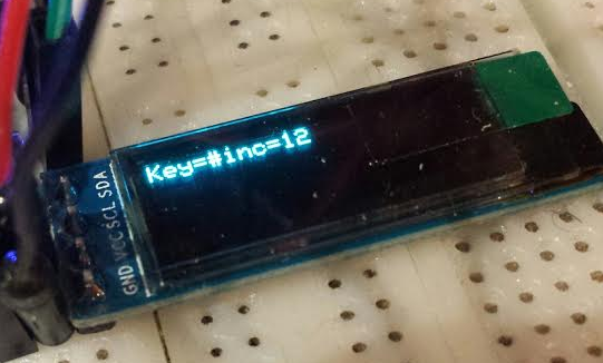
Off-topic: receiving data from the RN42
While the prototype does not need the RN42’s TX pin to be connected to the arduino to operate, I still experimented with it to read responses in command mode. What should have been a 5 minutes test turned out to be trickier than anticipated, so I capture a few notes here just in case.
The RN42 is configured to communicate at 115200 bauds by default, and it turns out that while the Arduino pro mini can send data on its TX pint at 115200bauds, it struggles to receives data at this rate, with results ranging from almost working but corrupting a few characters, to reading garbage.
The solution is to lower the baudrate to something lower (I used 9600 arbitrarily). There is a useful command on the RN42 to temporarily adjust the baudrate, without impacting the baudrate configured at power-up (115200). As a reference, the full sequence to read and display the RN42 firmware version as the response to the V command is :
// Enter RN42 command mode
Serial.print("$$$");
delay(50);

// By default the RN42 uses 115200 bauds in RX and TX
// But somehow the arduino pro mini cannot handle the 115200 bauds in the RX direction
// So set RN42 temporary baud rate to 9600
Serial.print("U,9600,N\n");

// Change baud rate on arduino TX side to 9600 too
Serial.flush();
Serial.begin(9600);
delay(250);

// Flush RX buffer just in case
while(Serial.available()) Serial.read();

// Enter command mode again
Serial.print("$$$");

// wait a bit to make sure response ("CMD") has started arriving
delay(5);

// read & display incoming response bytes
while(Serial.available()) {
display.print((char)Serial.read());
}

// Send command to get RN42 firmware version
delay(50);
Serial.print("V\n");

// wait a bit to make sure response (FW version text) has started arriving
delay(10);

// read & display incoming response bytes
while(Serial.available()) {
display.print((char)Serial.read());
}

// Exit command mode
delay(250);
Serial.print("---\n");

// wait a bit to make sure response ("END") has started arriving
delay(10);

// read & display incoming response bytes
while(Serial.available()) {
display.print((char)Serial.read());
}

// Restore arduino baud rate to 115200.
Serial.flush();
Serial.begin(115200);
Note: some of the delays are due to the fact that I reduced the UART RX buffer to 16 bytes earlier on, to optimize SRAM memory usage. So to make sure I do not loose any incoming character, I ensure through these delays (calibrated manually based on captured trace on the line) that the arduino start actively reading received bytes right after they start coming in.
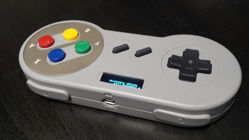
PROTOTYPE #3: the SNES variant
The next step was to package the prototype into something usable. That meant:
- integrating components into an enclosure
- running the setup off a battery
- and rationalizing the setup to a full 3.3V design, to get rid of the 5V/3.3V converter
Enclosure
I could have tried to design a custom 3D-printed enclosure, but this time I felt lazy and started browsing the web looking for ideas of devices that I could reuse to integrate my setup. I needed something with some space to fit the small OLED screen on the front, had a few buttons/wheels, and enough internal space to fit the arduino, EEPROM, RN42 module, and battery.
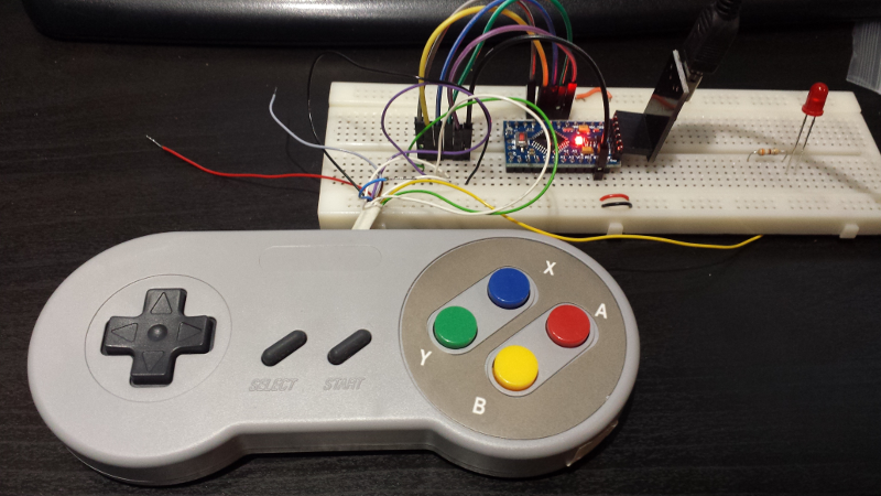
Something that would feel right to hold in my hands…I realized a gamepad would be perfect. So I bought this USB SNES controller clone on eBay:
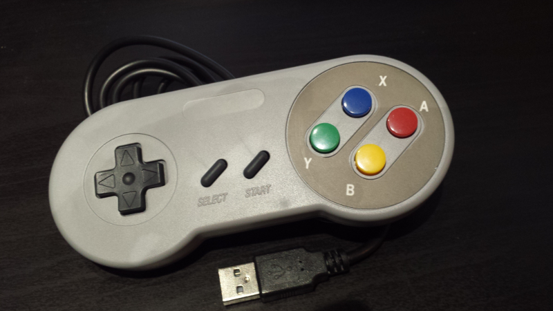
Note: I used jstest-gtk on Linux to check the controller was working fine, before hacking it.
Choosing this controller also meant replacing the rotary knob logic in the code with a simpler handling of the controller buttons state, so I updated the code to use discrete buttons to navigate the user interface.
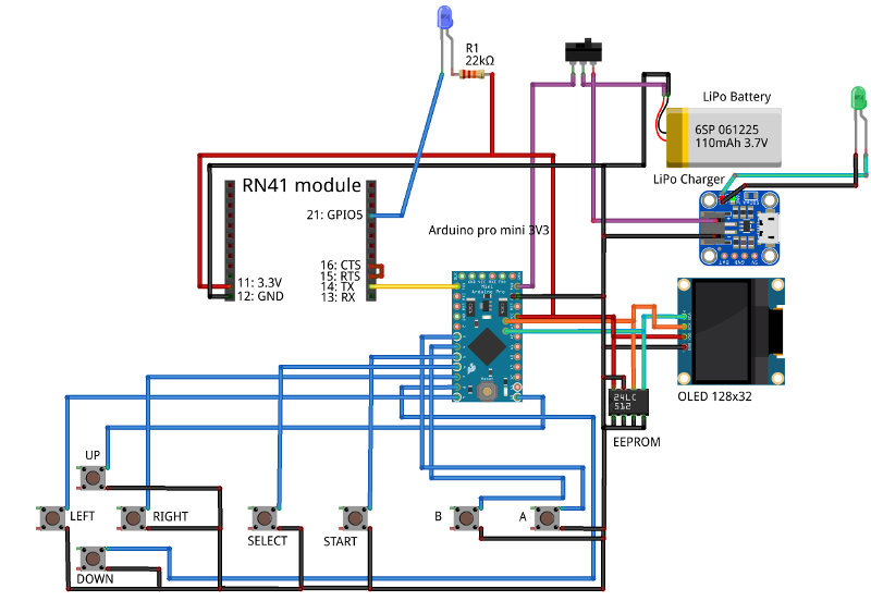
Full 3.3V setup
To simplify the design, I moved everything to 3.3V, to get rid of the 5V/3.3V converter
- I switched to a 3.3V version of Arduino Pro Mini
- the EEPROM is compatible with 3.3V (operating range is 2.5V-5.5V)
- the OLED display is compatible with 3.3V (operating range is 2.8V-5.5V)
- the RN42 requires 3.3V anyway
Important note when using 3.3V arduino: the onboard regulator producing the 3.3V supply only takes the RAW/VIN pin as input. The VCC pin that is on the programming header is connected to the internal VCC directly, so it is VITAL to use a 3.3V FTDI programmer, not a 5V one.
Battery
I wanted the battery to be small enough to fit in a small enclosure, and be rechargeable: a small LiPo battery was the obvious choice.
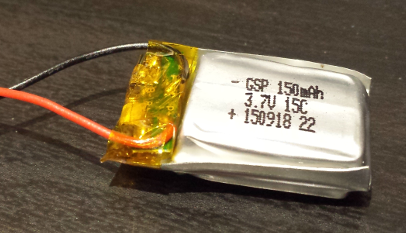
The charging part is managed through a small micro-USB LiPo charger from Adafruit (many others exist):
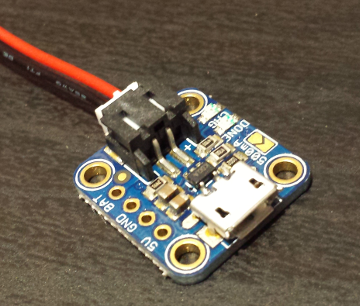
I used a 3-position switch to swap between battery-to-charger and battery-to-circuit connections, it also serves as on on-off switch when no USB cable is connected on the charger. The overall circuit draws around 10-15mA, so a very small LiPo e.g. 150mAh is good enough to last for many many uses before recharge.
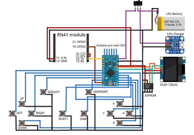
Updated assembly diagram
The 3.3V setup with battery and charger is as follows:
Integration
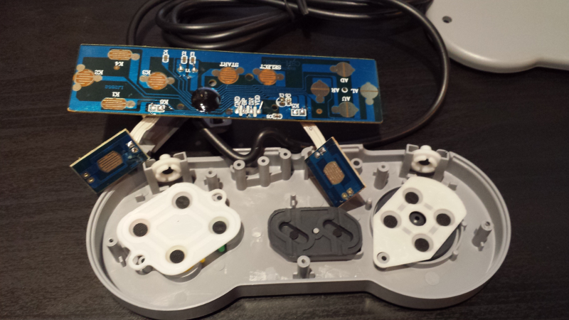
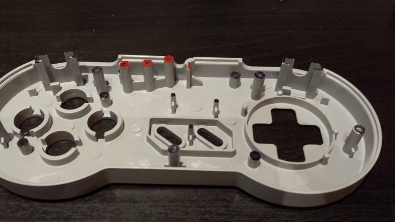
Opening the controller, I was reassured that there was plenty of space to fit the components:
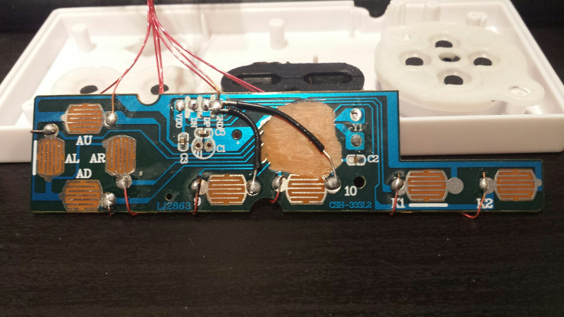
The rubber parts under each button guide the black conductive thingies onto the contact surfaces on the PCB. The black blob is the epoxy covering the USB chip:
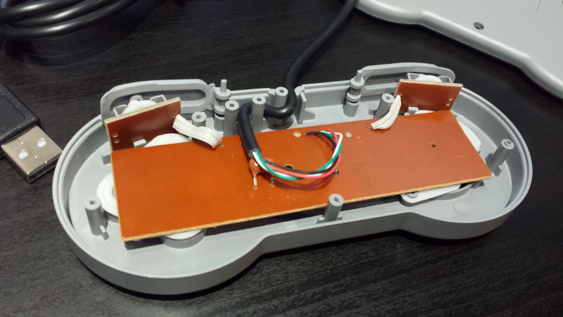
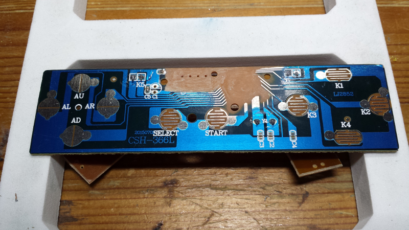
Since I wanted to reuse the PCB and contact surfaces only, I removed the active part (the electronics under the epoxy blob):
And soldered one wire per button, plus one wire for the gnd common to all signals:
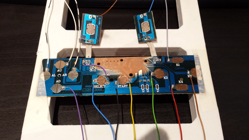
I tested the setup by connecting the buttons to GPIOs of the arduino: so far so good.
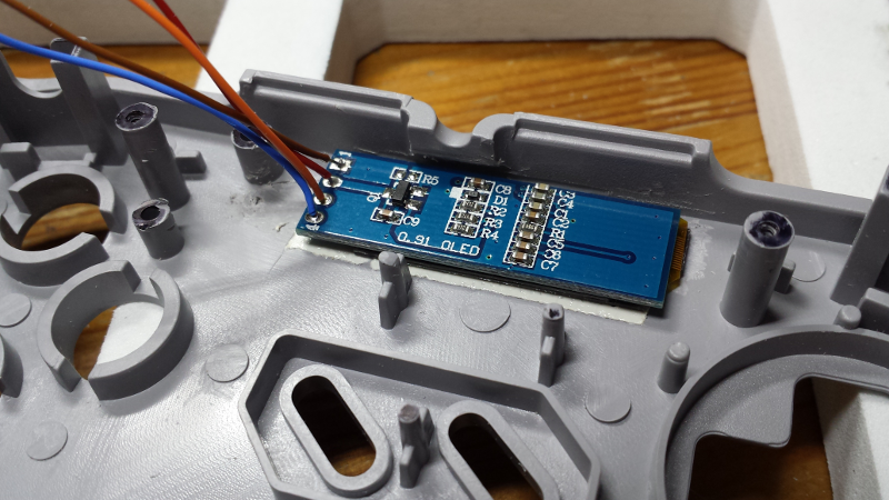
I identified some of the plastic pegs to be removed to be able to fit the display:
Then cut a square opening in the controller front face, and double-side-taped the display in front of the opening:
I checked the intended placement for the battery (a phone battery at the time of the photo, later replaced with a cheaper LiPo), RN42 module, LiPo charger, EEPROM, OnOff switch, and arduino: they nicely fit on the back of the original PCB:
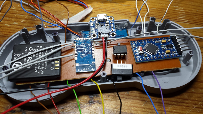
The finished assembly is a visual mess, but works just fine. I later added some hot glue to secure the exposed/weak wire solders.
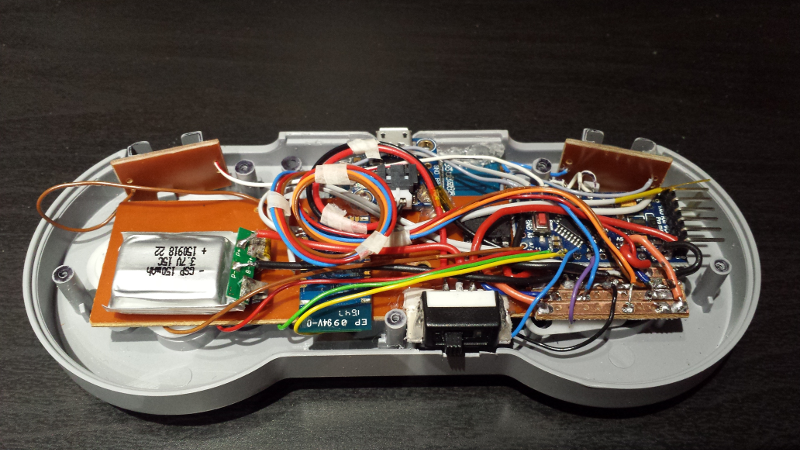
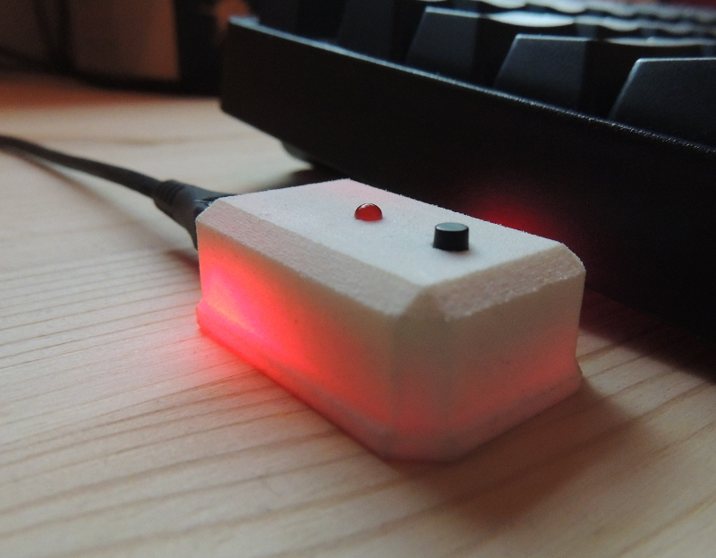
Finished device, with display and on-off switch at the bottom:

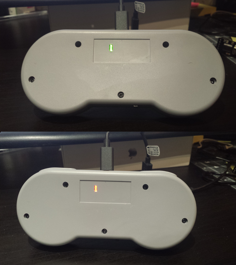
micro-USB charging port on the back, where the USB cable used to be:
The Adafruit microLiPo charger module has two LEDs on it: a red one that is lit during charge, and a green one that lits up when charge is completed. I cut an opening in the back of the controller, just on top of where these two LEDs are located, and used a small piece of transparent plastic to conduct light. This way I can check the charging status when a USB cable is connected:
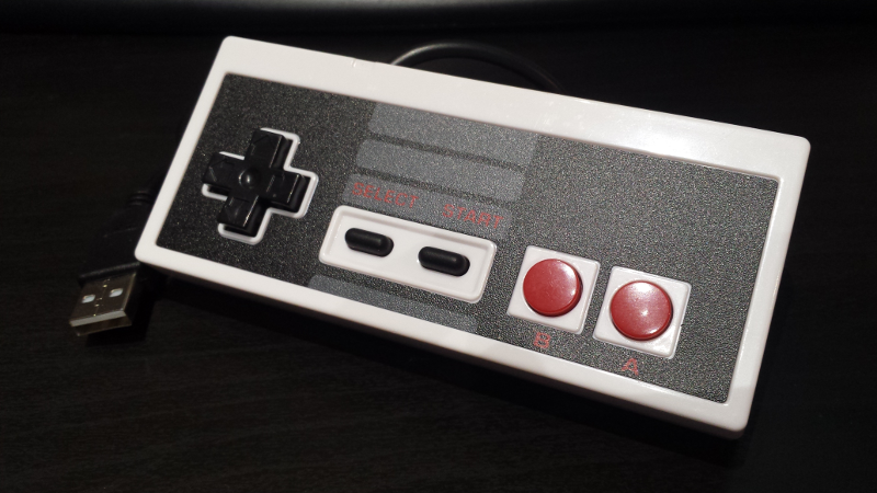
PROTOTYPE #4: the NES variant
I needed a second BlueKey anyway, so I couldn’t resist getting a NES controller clone and having a second go at integrating parts, and improving a few things in the process.
Enclosure
eBay to the rescue again, I picked the cheapest NES controller clone I could find:
Updated assembly diagram
The NES controller has less buttons (which is fine, several buttons of the SNES variant were left unused anyway), so I remapped actions to them. Also, I put the charging LED on the front (more convenient) and added an LED showing the bluetooth connection status (blinks during connection, and stays on when connection is successful)
Integration
First step, reuse the PCB and solder the wires:
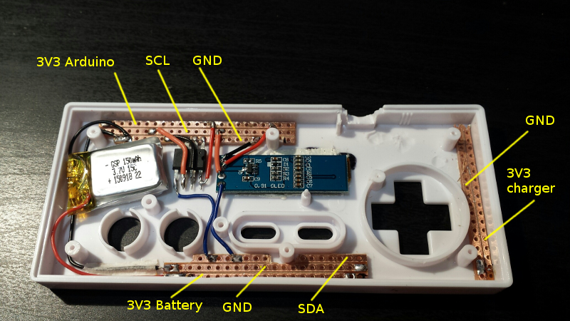
Next up, cut the opening for the display, glue it, find a spot for the battery. Also, I used a few strips of prototyping board to help (a bit) with the wiring:
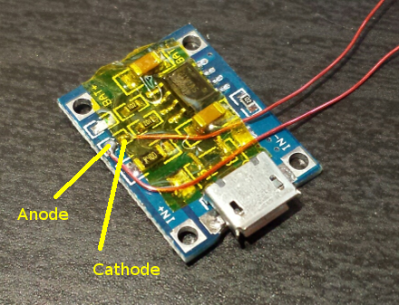
To show the charging status on the front of the controller, I just unsoldered the small SMD LED on the LiPo charger, and soldered a couple of wires to a (remote) 3mm LED:
Original PCB still fits, and is cut just enough to fit the shape of the USB LiPo charger (mounted face down):
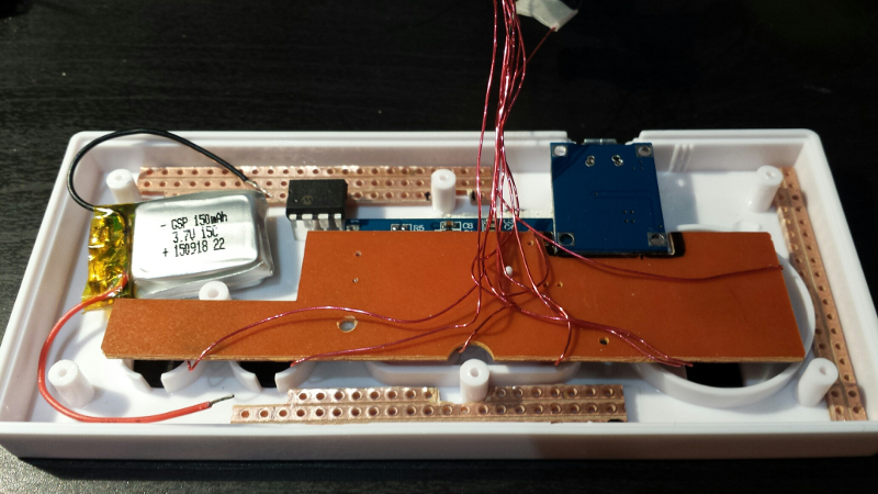
The complete version with the Arduino, RN42 module, power/charge switch, and the big mess of wires (the X’es are the places where the opposite plastic cover moldings come in contact with the PCB to hold it in place):
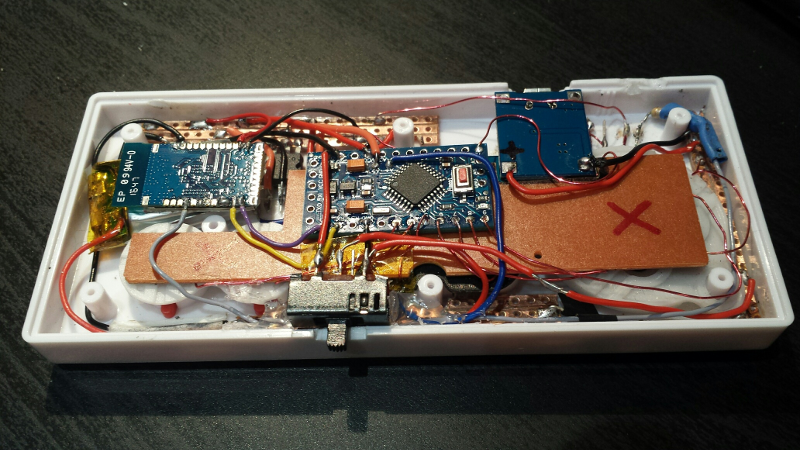
Et voilà, all done:
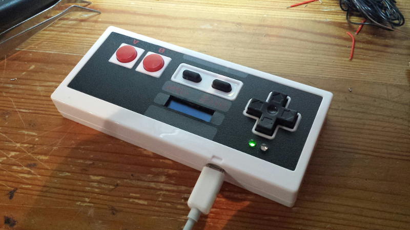
View of the microUSB charging port:
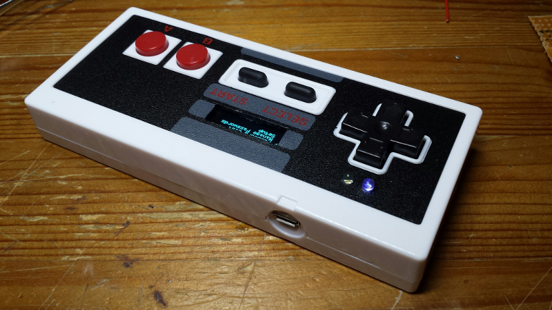
The green LED lits up when the switch is on the charging position and charging is in progress. It turns off when charging is complete.
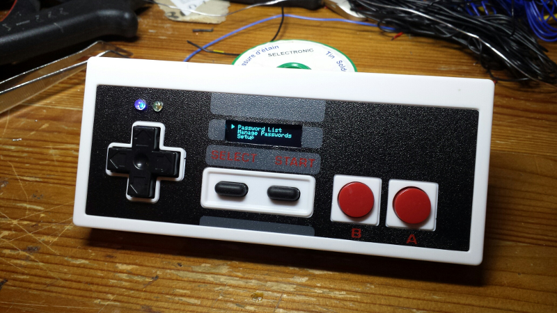
Using the BlueKey
Initial Power-on
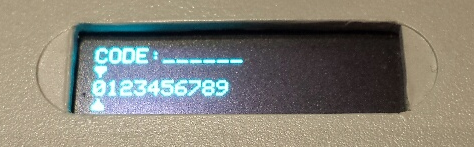
During the very first power-on, the EEPROM is empty, the device will detect it, format it, and ask for a user code:
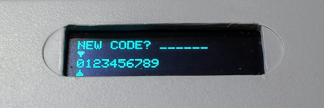
While entering the code:
LeftandRightarrows are used to navigate horizontally through number selectionY(green) button is used to confirm currently selected letterStartbutton is used to confirm
This code will then be used to encrypt all password data in the EEPROM. The user code must be entered a second time as a check:
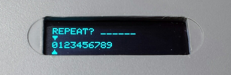
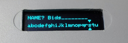
Should this user code be lost, there would then be no way to unlock the device or retrieve it, so choose with care. A username for the BlueKey must then be selected:
The EEPROM formatting is then launched:
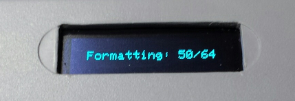
And the device is then ready to use.
Power-on & unlock device
When switched on, the login screen appears, prompting for the usercode to unlock the device:
Note: I arbitrarily used a 6-figure number format, but a longer alphanumeric unlock code could be used for the extra paranoid.
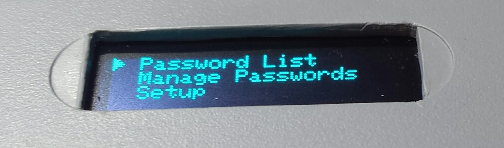
Main menu
UpandDownarrows are used to navigate vertically through screen entriesY(green) button is used to confirmA(red) button is used to cancel / go back to previous menu
Initial Bluetooth setup
The bluetooth configuration (mostly entering the bluetooth address of the device to be paired) can be accessed from the setup menu:
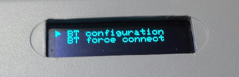
(the menu entry to force bluetooth connection is for test purposes and should not have to be used)
Initial pairing procedure:
- Get the bluetooth address of the remote device (e.g. phone) to be paired. On Android phones, it can be found in
Settings/About Device/Status/Bluetooth Address - turn on the BlueKey
- in the
Setupmenu, selectBT configuration, and input the remote device’s bluetooth address when prompted - From the remote device, launching the bluetooth pairing: the remote device should detect a bluetooth keyboard, and connect to it.
- turn off the BlueKey, and wait until it is detected as disconnect on the remote device
- turn on the BlueKey: it should connect automatically to the remote device.
Password list menu
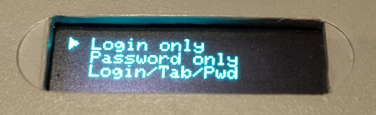
The account for which a login/password should be sent can be selected from the list of stored accounts:
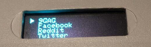
Once an entry is selected, the user can choose to send the login only, the password only, or a sequence of login + tab character + password (to fill most usual login/pwd fields)
Passwords management menu
The password management submenu allows to create/store a new password, to delete a password, to format the whole device, and to check the current number of passwords stored on the device:
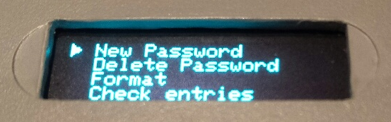
The master key/code is entered during the formatting procedure.
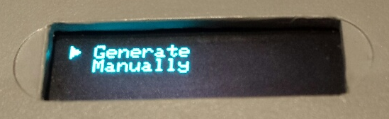
New entries can be created/stored either by letting the device generate a random password value of a specified length, and by entering the password manually
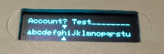
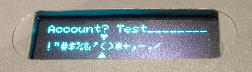
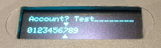
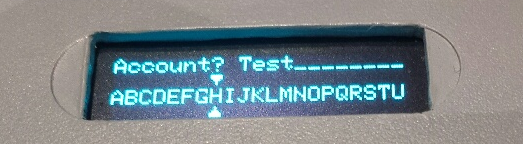
While entering text:
LeftandRightarrows are used to navigate horizontally through letter selectionY(green) button is used to confirm currently selected letterUpandDownarrows are used to navigate through available charsets: Uppercase letters, Lowercase letters, Numbers, Special characters.Startbutton is used to finish entry
A small video of the NES variant in action, using a dummy password on a random login page on an Android phone:
Display orientation
Due to the way I mounted the display in the controller, the text ended up showing upside down. No worries, the SSD1306 has a control command allowing to change the orientation of the display. Just call:
display.ssd1306_command(SSD1306_SEGREMAP ); //A0h
display.ssd1306_command(SSD1306_COMSCANINC); //C0h
instead of the original
ssd1306_command(SSD1306_SEGREMAP | 0x1); //A1h
ssd1306_command(SSD1306_COMSCANDEC); //C8h
present in the library by default
Display performance
I was initially concerned about performance of the OLED display refresh, since the Adafruit GFX library sends the full image buffer over I2C every time the “display.display” function is called.
There is an opportunity to optimize this by only sending the updated sections of the screen to the device, but in fact updating the full 128x32 display over I2C only take about 20ms, so it is not a true limiting factor in my case.
The only obvious precaution I took it to make sure to minimize the number of calls to display.display.
Todo list
- Export/Backup function (dump encrypted EEPROM content over bluetooth, for storage/backup on external device)
- custom sticker to replace the original A/B/X/Y sticker on the SNES variant, to show the use of each button
Source Code
The source code is available here.
Afterthoughts
I learned about the existence of the Mooltipass only after completing this project. It looks like an excellent pro-quality device, but is a wired device like the FinalKey (and is not cheap either).
Lessons learned
- The initial prototype was assembled very quickly, with cheapo components from ebay that worked out of the box: I just love the arduino ecosystem.
- I need to improve my soldering skills…I almost killed the tiny RN42 module while soldering it.
- I never thought that implementing an emulated Bluetooth keyboard would require close to zero effort when choosing the right BT module: RN42 is worth every penny.
- The arduino IDE is such that it only compiles/links the library functions that are actually called in the main sketch. This is extremely cool when using a single function of a large library.
- The 2048 bytes of Arduino mini SRAM are precious and should be watched closely, otherwise evil things happen and countless debugging hours ensue.