LED Matrix Strip
This project started when I stumbled upon these dirt-cheap LED matrix modules on eBay. I had no real need for them, but the fact
that each module/kit came with its own MAX7219 chip made it more than worth the purchase anyway, since buying standalone MAX7219 is usually (much)
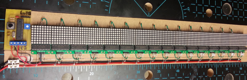
more expensive than that. 3$ shipping cost included, hard to beat. So I bought 20 of those, and decided to combine them into a single display driven by
an Arduino board.
- HW Part : LED Matrix module
- HW part : Arduino
- HW Part : Power supply
- SW part : Arduino
- Custom PCB
- Bluetooth upgrade
- Lessons learned
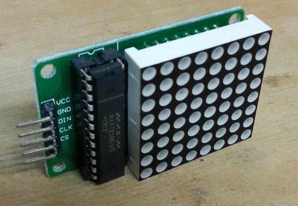
HW Part : LED Matrix module
These modules are delivered completely unassembled, so it required manual soldering. Nothing too difficult, but at about ~60 solder points per module, assembling the 16 modules took…a while.
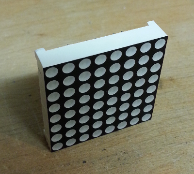
Here is the 8x8 LED matrix itself:
Front :
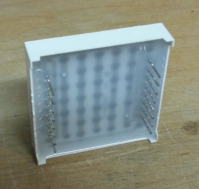
Back :
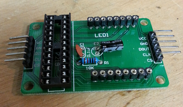
And here is a view of the assembled PCB, just before attaching the MAX7219 chip and the LED matrix:
The final assembled module:
Note that the matrix is symmetrical, and there was no indication as to the required orientation for plugging it on the PCB. A few trial & error tests on a protoboard, along with checking the routing of tracks on the PCB, allowed to figure out the right orientation.
SPI communication refresher
A few words about the SPI (Serial Peripheral Interface) communication link that will be used to communicate with the LED Modules, since this is what the MAX7219 requires. This synchronous master/slave protocol relies on four signals :
- a Serial Clock (SCLK) signal, driving the sending/receiving of data bits
- a Slave Select (SS) signal, allowing to enable/disable communication with some or all of the slave devices
- a Master Out - Slave In (MOSI) signal, carrying the data bits being sent from the master to the slave(s).
- a Master In - Slave Out (MISO) signal, carrying the data bits being received by the master, from the slave(s). There are various flavors of this base concept (depending on the desired clock polarity and phase).
Considering this, the input pins labelling is quite straightforward:
- VCC and GND for supplying power (5V)
- DIN is “Data In”, i.e. the MOSI signal
- CLK if the “Clock” pin, that will be driven by the SPI master
- CS is the “Chip Select” pin, also driven by the SPI master
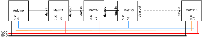
The output of the module is similar, with DOUT being the “Data Out” pin, which will be used to daisy-chain the output of one module to the input of the next one. For this particular project, there are 16 daisy-chained SPI slaves, sharing common CLK and CS lines. There is no need to manage the modules as 16 independent slaves, since we will always refresh the full display anyway. Also, since there is no need to receive any data from the modules, the MISO signal will be left unused at the SPI master side (i.e. on the Arduino).
So, here is the overall view on the principle of the project:
HW part : Arduino
As usual, I started with using an actual Arduino board (Uno, in this case) to prototype to circuit. The setup is as follows:
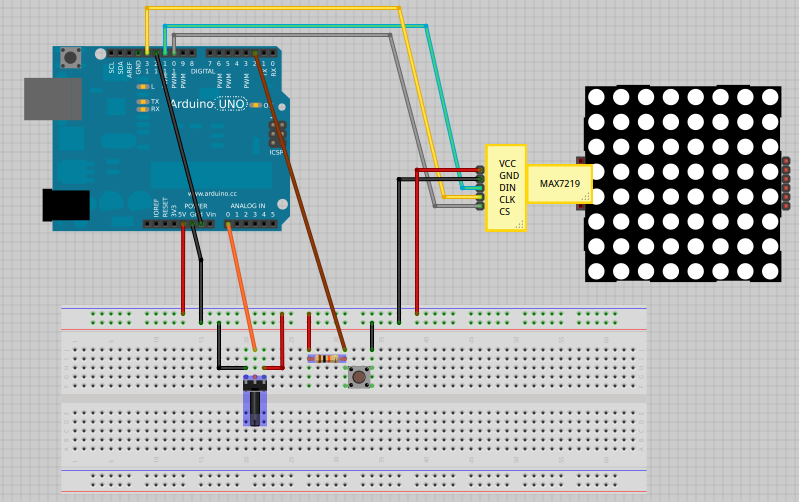
Note that pin 12, allocated to the MISO (Master In - Slave Out) SPI function in the code, is linked to ground, since we are not reading any SPI data back from the LED matrices anyway. he potentiometer is used to allow the user to adjust the scrolling speed: since one or its leads is grounded, and the other it at VCC, linking the middle lead to analog input pin #0 on the Arduino allows the SW to read a value between 0 and 5V, and convert that into a scrolling speed. The pushbutton, when pushed, connects the digital input pin #2 to GND, else it is pulled high to VCC (through the 10k resistor). The SW can therefore read the state of the pushbutton by checking if digital pin #2 is HIGH or LOW.
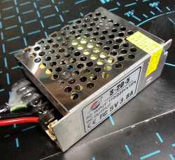
HW Part : Power supply
When using just a few daisy-chained LED matrices, the power supply from the arduino is enough. It is quite easy to consider that these are just a few LEDs, not drawing too much current anyway. But this particular project has 16 matrices of 8x8 LEDs, so 16x8x8 = 1024 LEDs total. A thousand LEDs each drawing say, 20mA, and we would be drawing 20 Amps (!). But a few factors come into the picture:
- in most cases, not all LEDs will be on at the same time. Still, this case must be taken into account.
- the MAX7219 allows to set the intensity of the LED matrix display, so we can adjust the intensity to a small value to limit power consumption.
- but above all, the MAX7219 internally uses a nice trick: it does not turn on all the active LEDs of the 8x8 matrix it controls at the same time, but instead turns the 8 rows on/off in a sequential manner. This row scanning is performed at a very high speed (800 Hz), so to the naked eye it looks as if all 8 rows are always active. The big difference though is on power consumption: since only one row is active at a given time, the full matrix consumes 1/8 of what the 64 LEDs would normally draw.
- In the end, the worst case consumption I measured in my case is about ~3.3 Amps.
After a few failures trying to use (too) small 5V power supplies, I finally picked a 5V 3.8Amps supply (8$ at DealExtreme, shipping included) that would support the worst case current draw.
SW part : Arduino
The arduino software for this project is quite simple, given the availability of libraries for SPI communication with the LED matrices.
setting up SPI
Originally, I used the LEDControl library, starting from the LCDemoMatrix example provided with the arduino IDE. It uses pin 12 for SPI data output, pin 11 for
the SPI clock, and pin 10 for the SPI “LOAD” (i.e. CS).
The required data in arduino memory representing the values of the 16x8x8 LEDs are stored as a buffer of 16x8 bytes (i.e. 1 bit per LED state). Since I intended to have a horizontal strip of 16 LED modules, the natural thing to do was to organize these bytes so that the first byte corresponds to the first 8 pixels of the first row, the second byte corresponds to the next 8 pixels on the same row, etc…as would be the case for the video RAM of a regular display.
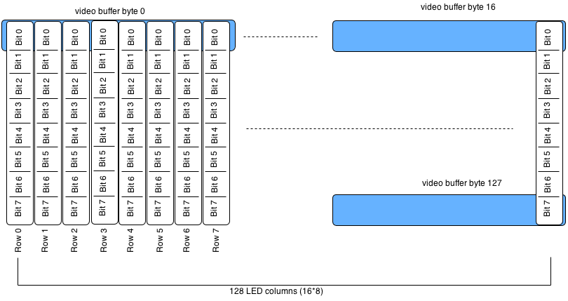
But in this specific case, given the physical orientation of the modules, what the MAX7219 considers as “rows” are actually the columns of the 8x8 matrix, so we need to send out the data column by column. This means reconstructing the column bytes from the row bytes. This is not difficult, but it does mean that lots of CPU cycles would be used just for re-arranging the data, each time the LED matrices are updated. The performance implications are far from being negligeable on an Arduino. So instead, it is better to store the data directly in a column-friendly format :
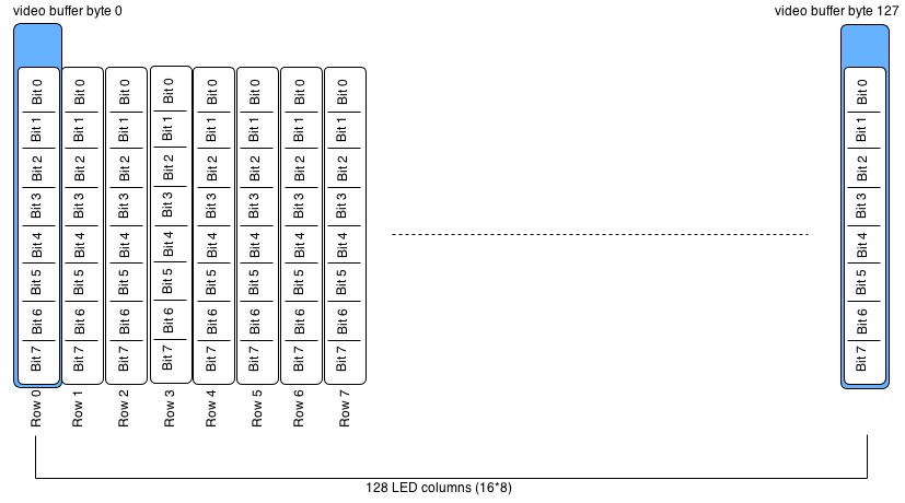
This way, the bytes of the buffer can be sent as is to the led matrices, one after the other, to update the corresponding columns.
So to update the Xth column of all 16 modules in the display, we must prepare this buffer of data:
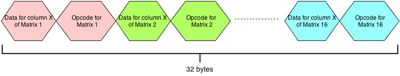
Finally, since the 16 modules are daisy-chained and module 16 is at the end of the chain, we must send out the data beginning by the end of this buffer, from right to left.
This worked fine, however I soon encountered a performance issue: even with this daya layout, when using that many LED matrix modules,
refreshing the full display takes a significant amount of time, therefore limiting the display refresh rate. Taking a closer look at the LedControl library, I
noticed that it performed the SPI data transfer by programmatically sending out the data bit by bit (i.e. “bit banging”). The library does it this way to be as flexible as possible regarding the mapping of the Data pin, but the downside is that it does not use the built-in (i.e. in HW) SPI capability of the arduino
(available on pins 10,11,12 and 13 on the Arduino Uno board). The SPIlibrary does make use of these pins, and is therefore able to send out data much faster that
with bit banging. The SPI sending frequency can be set through setClockDivider, and the fastest setting is SPI_CLOCK_DIV2, which will run the SPI transfer at 1/2 the frequency of the arduino (1/2 x 16 MHz in my case).
Using the SPI library and SPI_CLOCK_DIV2 speed setting, I got at least x10 faster operation, allowing to refresh the display often enough to produce visually
smooth scrolling.
Drawing Letters & Pixels
There are two cases to manage :
- Drawing a character, from a 8x8 font, at a given offset x
- Drawing an individual pixel at location (x,y)
To efficiently draw characters into the buffer, the font is stored as a series a column data, so the only remaining job to draw a given letter is to copy the 8 bytes corresponding to the 8 columns of this letter, at the appropriate offset in the buffer. In fact, the font is defined in the code as series of bytes representing the line-by-line values, since this is easier to find, and the letter are then all converted into the column-based format using a specific rotateFont function, called once at startup.
To draw individual pixels in arbitrary (x,y) locations, the line-to-column bit manipulation ares still required, to be able to keep the natural (x,y) coordinate system. At least this is a performance compromise I am willing to make, to keep the pixel-related code clear enough. Since we usually don’t draw that many individual pixels anyway, the performance impact is ok.
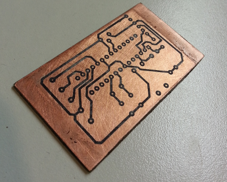
Custom PCB
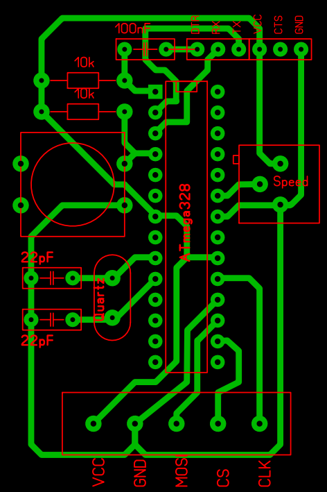
Since the Arduino setup worked fine, it was time to switch to a homemade PCB. The PCB integrates the minimum components required for the project:
- the ATmega328 chip programmed with the Arduino Uno bootloader (about ~3 euros on eBay)
- a 16 MHz quartz with its two filtering capacitors
- a potentiometer for adjusting the scroll speed
- a push button to switch between display modes
- two pull-up resistors (one on the reset pin, another one one the pin that the push button uses)
- a header for connecting power and the signals for the LED matrices
- another 6 pin header for FTDI programming of the arduino
Etching was done using this method
Here’s a snapshot in the middle of the process:
And a view of programming the ATmega using a FTDI cable:
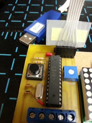
Final assembled project :
Notice the particularly messy soldering work, and hacked connectors. Still, it works. At this point, changing the messages on the display required updating the Arduino code, then plugging a cable on the top header of the PCB, and launching the download from the Arduino IDE.
Bluetooth upgrade
To be able to customize the displayed messages/animations more easily, I considered adding a wireless communication module. There are many options to choose from (WiFi, XBee, Bluetooth, RF, …) and for lack of a better reason, I went for a cheap one after finding a bluetooth module for 8$ on DealExtreme (“JY-MCU Bluetooth Wireless Serial Port Module for Arduino”):
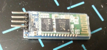
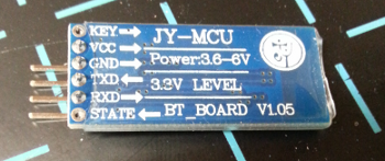
It doesn’t get any easier than this: VCC and GND for supplying power (5V from Arduino), and RXD/TXD to send/receive the data through serial communication.
Even though the module works just fine out of the box, you may want to change a few of its internal settings. The way to do this is to connect to the module over its serial line (using whatever mean, I used my FTDI cable and launched a minicom terminal on /dev/ttyUSB0…), then send a few “AT” commands to configure the device. Note that to make sure the command being sent is read entirely, it is better to prepare the command in a text editor somewhere, then copy/paste the full command into the serial terminal.
AT: will print out “OK” in return if everything is working.AT+NAMEmycustomname: sets the Bluetooth device name to “mycustomname”, prints out “OKsetname” if successful.AT+PINxxxx: sets the PIN code to xxxx, prints out “OKsetPIN” if successful.AT+BAUDx: sets the baud rate to speed number x (4 for 9600 (default), 8 for 115200)
For this project, 9600 baud rate is ok for me, so I just changed the device name for something easily recognizable (“LEDdisplay”) and adjusted the PIN number (not that I cared if anyone hijacked my LED display…)
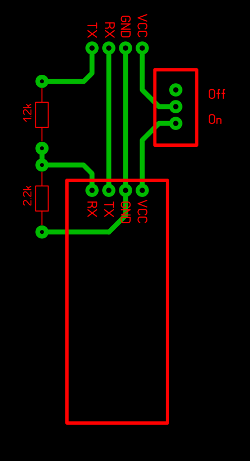
Since I needed a way to attach this bluetooth module to the rest of the LED strip, I created a small PCB to host it, and deal with two required tricks at the same time:
-
The BT input/output pins use 3.3V logic, whereas my arduino chip only supported 5V logic. Even though my initial tests showed that it just worked anyway, it was better to include a voltage divider between the TX output of the arduino and the RXD input pin of the BT module. A 1.2k and a 2.2k resistor did the job. In the other direction (from BT TX to Arduino RX), no voltage scaler is required since the arduino will take the 3.3V logic just fine.
-
The BT module RX/TX will be connected to the TX/RX of the arduino, via the same connector as the one I use for plugging the FTDI programmer. To avoid any problems due to having both the programmmer and the BT module connected on the same pins, I added a simple switch on the VCC of the BT module. This way, when the switch is off, the FTDI programmer has exclusive access to the arduino TX/RX lines.
On the Arduino software side, communication with the BT module is quite easy, since it is standard serial communication. Using the Serial built-in library allows to write/read characters to/from the module. In practive, the serialEvent callback function was implemented to handle data reception, and notify the main loop when new data is available. This serialEvent callback gets called (behind the scenes) after each the main loop execution.
I (arbitrarily) chose a string format @<cmd>@<data>@ as the pattern that the arduino will try to decode while receiving individual bytes
of data over this serial connection. A quick way to test that communication is ok and that the Arduino decodes the commands properly is to use the “BlueTerm” android application from a smartphone, and type in a string of this format.
The full source code is available here.
On the host side:
-
find the device’s MAC address using
hcitool scan -
modify
/etc/bluetooth/rfcomm.confto specify MAC address and name the device:
rfcomm0 {
        bind no;
        device <MAC address here>;
        channel 1;
        comment "LED display";
        }
- connect to the device:
sudo rfcomm connect 0 - finally interact over a serial terminal , for example using minicom, on port
/dev/rfcomm0
Lessons learned
- Watch the wire lengths. Long wires are fine when testing one of two modules on a protoboard, but when chaining more than 10 of these MAX7219 modules, the noise/distorsion introduced by the wires is enough to corrupt the data arriving at the last modules.
- Using “common rails” for CLK and CS worked better than daisy-chaining the signals from the output of one module to the input of the next.
- Estimate the power consumption beforehand.
- Triple check the wiring before applying power. I burned two MAX7219 along the course of the project.
- When possible, use HW-supported SPI communication instead of SW bit-banged SPI, for (much) faster communication.
- Adding Bluetooth communication to an Arduino project is quite straightforward, and not that expensive.