Wake an Android device with a PIR sensor
The purpose of this project was to have the ability to turn on an Android device automatically upon detection of human presence nearby.
Introduction
I happen to have a ViewSonic VSD220 Android wall-mounted tablet (see here) in the hall, centralizing various home automation applications. To save power, the screen turns off after 2 minutes. So to check the application statuses or do anything on the tablet, I had to push the power button to wake it, and wait for a second or so. After a while I realized that this (very) minor inconvenience was actually limiting the added value of the tablet: when passing by, I would not bother turning it on for a quick glance at the info on the screen. So I looked for a way to always have the screen turned on anytime I came nearby, and still let it go to sleep mode when I was away.
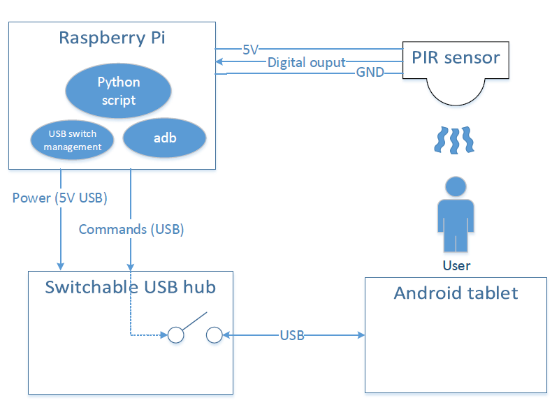
Any mechanism using HW/SW on the tablet itself (camera, microphone) would be pointless, since by definition it would be sleeping when the presence detection is required. So I used an external presence sensor, driven by a Raspberry pi (that was already there for other purposes), and leveraged the USB debug connection to the device to turn it on:
- a PIR (Passive Infra Red) sensor is used to detect presence in a large area in front of the tablet. The discrete output from the sensor notifying of a detection is read by one GPIO pin of the raspberry pi.
- a Python script monitors this GPIO, and sequences actions upon presence detection.
- the
adbexecutable from Android SDK is used to communicate with the tablet over USB, to turn it on. - a switchable USB board is used, to allow powering off USB completely once communication is not required anymore.
- three USB cables are involved.
HW setup
PIR Sensor
Any cheapo PIR sensor will do, I got this one for 2$ from China. It has:
- a three-pin header with 5V, GND, and OUTPUT
- two potentiometers to adjust sensitivity and cooldown time
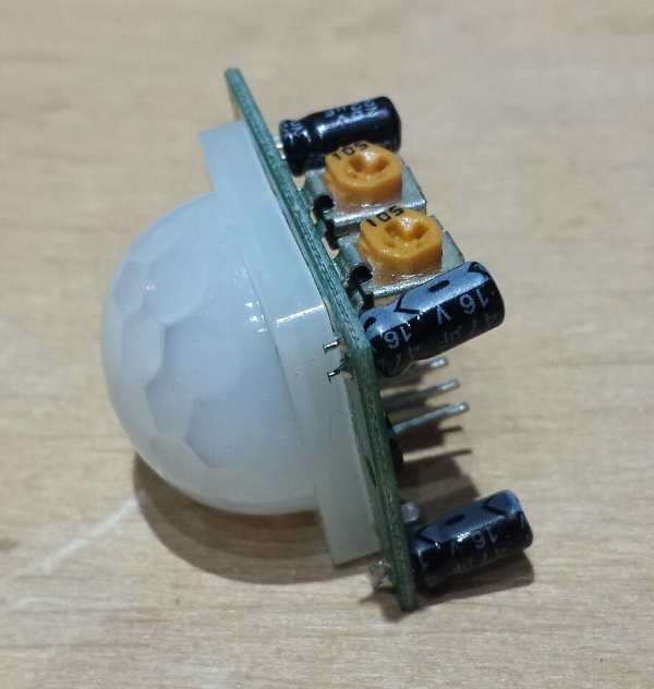
Whenever it detects something in its field of view, the output pin goes HIGH, and stays high for some time (depending on the potentiometer setting), and returns to low state.
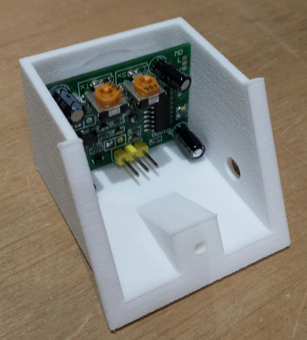
Since the sensor will be mounted on the wall above the display, I designed a small holder and had it 3D-printed (at Sculpteo, this is the third object I have printed there, and I am quite pleased with the quality vs. price):
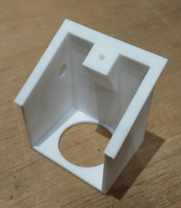
The Sketchup 3D model and exported STL file are available here.
The PIR sensor fits nicely in there:
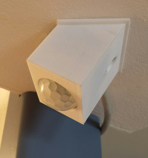
And here it is attached to the ceiling above the display:
Raspberry Pi
Three pins from the GPIO header must be connected to the sensor:
- a 5V pin (I chose pin 2)
- a GND pin (I chose pin 14)
- any GPIO pin (I chose GPIO4 / pin 7)
YKush USB switch
This part should not be required, BUT it turns out that when the VSD220 tablet detects that a (powered) USB cable is connected, it will never go to complete sleep mode. It will stay with the screen dimmed but not OFF, which I considered unacceptable. Since I did not want to mess with the Android SW in the VSD220 itself, I used a simple (yet slightly expensive) workaround: a USB board that has the capability to switch off power on each of its output ports on command. I happened to have such a board (YKush from Yepkit) that was lying around, and it was the perfect opportunity to put it to good use.
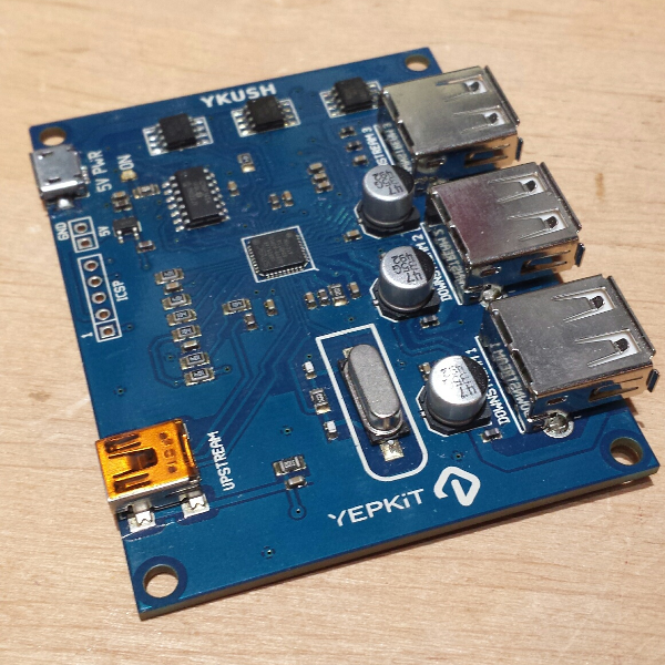
The board has two inputs:
- a mini-USB port for communication
- a 5V power input, that can be supplied either through a dedicated connector or more simply through a micro-USB connector
Just like any powered USB hub, the 5V input power should ideally come from a dedicated external power supply. However, in my usecase I am not going to plug anything else than the USB cable to the tablet on this board, so the power draw will be very small, nothing that the Raspberry’s USB ports cannot provide. So I just plugged two USB cables, one mini-USB and one micro-USB, between the YKush and the raspberry.
Ideally, a much simpler solution would be to use a simple transistor to switch the 5V of the USB cable on and off, commanded directly by a raspberry GPIO.
USB cable
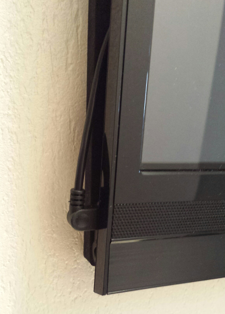
Unfortunately, the micro-USB plug on the VDS220 is not located in the back of the screen, but on the left side. Since I wanted to keep a USB cable plugged permanently in there, I did not want to see a big connector sticking out along with a large loop of cable, so I ordered a cable with a right-angle micro-USB connector. The cable is still visible, but it does not look too bad, and at least there is no chance to inadvertently unplug it:
SW setup
The raspberry is installed with a default Raspbian image.
GPIO python library
The RPi.GPIO python library should be available by default in the raspbian distribution. The Pi I used had a quite old version installed, and to solve a bug in the GPIO management I had to update to the latest version of this library:
sudo apt-get install python-rpi.gpio
Compile ykush utility
A simple command line utility is available from Yepkit’s website to manage the YKush board. I compiled it this way:
sudo apt-get install libusb-1.0-0-dev libusb-1.0-0
wget https://www.yepkit.com/uploads/documents/fd484_ykush_v1.4.1.tar.gz
make
The resulting ykush executable then provides a few very simple commands to control the USB ports, and I only used two:
To turn one of the three ports:
ykush -d [port number]
To turn it off:
ykush -u [port number]
I archived this executable binary (for raspberry 1 & 2) here.
Compile adb
These useful instructions were used to compile a version of android SDK’s adb tool, that is the almighty command line utility to communicate with an android device over USB. The version compiled below is old, but for such a simple task as sending a key input command, it works fine, and using a very specific git tag to get source code and build it provides some level of protection against evolutions of the source code that might break these instructions. Anyway, here they are:
sudo apt-get update
sudo apt-get install git build-essential libncurses5-dev libssl-dev
mkdir aosp
cd aosp
git clone https://android.googlesource.com/platform/system/core.git system/core
git clone https://android.googlesource.com/platform/external/zlib.git external/zlib
cd system/core
git checkout 32e2f1be039482762303378113c817ba99466953
cd ../../external/zlib
git checkout 8d977782c1cfe9d75cc9a464439c2ff1e27e1665
cd ../..
cd system/core/adb
Then create a Makefile file in this directory with the following content:
SRCS+= adb.c
SRCS+= adb_client.c
SRCS+= commandline.c
SRCS+= console.c
SRCS+= file_sync_client.c
SRCS+= fdevent.c
SRCS+= get_my_path_linux.c
SRCS+= services.c
SRCS+= sockets.c
SRCS+= transport.c
SRCS+= transport_local.c
SRCS+= transport_usb.c
SRCS+= usb_linux.c
SRCS+= usb_vendors.c
SRCS+= adb_auth_host.c

VPATH+= ../libcutils
SRCS+= socket_inaddr_any_server.c
SRCS+= socket_local_client.c
SRCS+= socket_local_server.c
SRCS+= socket_loopback_client.c
SRCS+= socket_loopback_server.c
SRCS+= socket_network_client.c
SRCS+= load_file.c

VPATH+= ../libzipfile
SRCS+= centraldir.c
SRCS+= zipfile.c

VPATH+= ../../../external/zlib/src
SRCS+= adler32.c
SRCS+= compress.c
SRCS+= crc32.c
SRCS+= deflate.c
SRCS+= infback.c
SRCS+= inffast.c
SRCS+= inflate.c
SRCS+= inftrees.c
SRCS+= trees.c
SRCS+= uncompr.c
SRCS+= zutil.c

CPPFLAGS+= -DADB_HOST=1
CPPFLAGS+= -DHAVE_FORKEXEC=1
CPPFLAGS+= -DHAVE_SYMLINKS
CPPFLAGS+= -DHAVE_TERMIO_H
CPPFLAGS+= -DHAVE_OFF64_T
CPPFLAGS+= -D_GNU_SOURCE
CPPFLAGS+= -D_XOPEN_SOURCE
CPPFLAGS+= -DWORKAROUND_BUG6558362
CPPFLAGS+= -I.
CPPFLAGS+= -I../include
CPPFLAGS+= -I../../../external/zlib

CFLAGS+= -O2 -g -Wall -Wno-unused-parameter
#LDFLAGS= -static
LIBS= -lrt -lpthread -lssl -lcrypto

TOOLCHAIN=
CC= $(TOOLCHAIN)gcc
LD= $(TOOLCHAIN)gcc

OBJS= $(SRCS:.c=.o)

all: adb

adb: $(OBJS)
	$(LD) -o $@ $(LDFLAGS) $(OBJS) $(LIBS)

clean:
	rm -rf $(OBJS)
And finally compile adb:
make adb
the resulting adb binary should be put in the same directory as the script.
I archived the resulting binary (for raspberry 1 & 2) here.
Setup USB device access rights
To be able to access the android device over USB without root permission, I created a file 51-android.rules in directory /etc/udev/rules.d/, with the following content:
SUBSYSTEM=="usb", ATTR{idVendor}=="0408", MODE="0666", GROUP="plugdev"
Of course, the “0408” vendorId should be modified to suit the vendorId of your specific device.
Python script
As usual, since there is no strong performance constraint anywhere in this project, a python script to manage the overall logic is just fine. The script’s sequence is detailed step by step below, and the source code is available here.
Initialise GPIO pins
The selected GPIO receiving the sensor signal is configured as an input, with pull-down when inactive. Once this is done the script perform the following steps in an infinite loop.
GPIO.setup(SENSOR_PIN, GPIO.IN, GPIO.PUD_DOWN)
Wait for detection
Wait for a rising edge on the input GPIO, using the interrupt-driven mechanism provided in RPi.GPIO library. This way no CPU cycles are lost polling the GPIO value.
RPi.GPIO.wait_for_edge(SENSOR_PIN, GPIO.RISING)
Wake device
Turn on the USB port towards the device, using ykushutility:
./ykush -u 1
And then wait until USB communication becomes available. Indeed, after powering the USB port, there is a delay before the device on the other end detects it (on my device, it is about 4 seconds). This active wait is done by continuously executing the adb devices command, until the deviceID of our device shows up in the output.
Note: the expected deviceID is specified in the .iniconfig file.
Then useadb to send a simulated user input corresponding to the action of waking up the device:
./adb shell input keyevent 224
Note: 224 is KEYCODE_WAKEUP, which behaves similar to key event “power” but has no effect if devices is already awake.
Wait for screen off
After whatever timeout value is configured inside the device, it will try to go back to sleep mode. To detect when this happens, we regularly execute this command:
./adb shell dumpsys power
and check whether mPowerState=0 is present as part of the output. On the (ancient) android version that runs on the VSD220, this is a sign that screen is being turned off after the timeout. Other keys on the dumpsys output might be used for other versions of Android.
Note: if during that wait time a new detection is made, we resend a wake command: this will have the effect of restarting the wake timer inside the device, so that it stays on as long as someone is nearby.
Prepare for sleep
For some reason, while USB is connected/powered the VSD220 device will never go back to complete sleep. So we switch off power on the USB port, which is equivalent to physically unplugging the cable, to give the device an opportunity to go back to full sleep mode.
./ykush -d 1
Prepare for next wake
This is just an optimization to allow a better reactivity when the next detection/wake happens: since USB communication is not available immediately after powering the interface, we turn it back on now, in advance. The only pitfall is to not turn it back on too quickly, because at least on my VSD220 it takes about ~15 seconds between the moment the screen goes off, and the moment the device enters full sleep mode (with screen completely off, not just dimmed). So after 30 seconds, the scripts turns USB power back on:
./ykush -u 1
Note that this 30 seconds wait is performed using a wait_for_edge call with a 30s timeout: this way, if a new detection occurs within this delay, we can catch it and handle it properly
Lessons learned
- The RPi.GPIO library rocks, and with a recent enough version of it the
wait_for_edgefunction allows to keep the CPU impact of monitoring a GPIO pin to the minimum. - Using a PIR sensor is straightforward.
- Just like for USB, it seems like having an Ethernet cable connected to the VSD220 somehow prevents it from going to full sleep too. I did not investigate.