RS485 sniffer
I had a need to monitor data exchanged between two nodes of an RS485 communication link, with the following requirements:
- the monitoring must be transparent to the nodes, i.e. it must be a passive spy/sniffer on the line.
- the sniffer must support sniffing raw UART data on an RS485 line running at a 1 Mbit/s bitrate over a twisted pair of wires, with standard UART settings (1 start bit, 8 data bits, no parity, 1 stop bit), and a dataflow of 1 message of 120 bytes every 20ms.
- captured data must be timestamped with a 1 µs resolution.
- captured data must be sent over Ethernet to a remote logging station.
- data protocol (if any) is managed offline by parsing/post-processing the log files.
- the sniffer must support 24/7 operation, so it must be extremely reliable.
Table of Contents
- Table of Contents
- Introduction to RS-485
- HW setup
- Test setup
- Arduino SW
- Remote host data logging SW
- Enclosure
- Robustness testing
Introduction to RS-485
RS-485 is the common/short name for referring to the electrical standards for digital communication described in TIA-485 / EIA-485. It’s a sibling of the well-know RS-232 standard, with two main characteristics that set it apart:
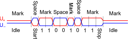
- it uses differential signalling over a pair of wires. I borrowed the following diagam from Wikipedia: a (significant) positive voltage between the + line and - line is interpreted as a 1, while a negative voltage of the same amplitude between + and - is interpreted as a 0:
- it allows a bus topology with multiple nodes connected to the same wire pair: only one node at a time is allowed to drive the bus, while the other nodes must be in reception mode. Again I borrowed the following diagram from the MAX485 datasheet:
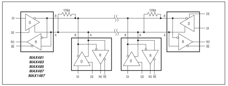
- each node can send data to the bus using its line driver (D) with its associated Driver Enable (DE) signal, and listen to data from the bus using its line receiver (R) with its associated Receiver Enable signal (RE)
- up to 32 nodes can be connected to the bus
- the two ends of the bus must have termination resistors, adapted to the impedance of the wire pair. 120 ohms is a typical value when using a twisted pair line to carry the differential signal.
In addition, it is good practive to have a pull-up resistor on the + line, and a pull-down resistor on the - line, to ensure a stable state (i.e. no data bits transmitted by mistake) when the line is not driven by any of the nodes.
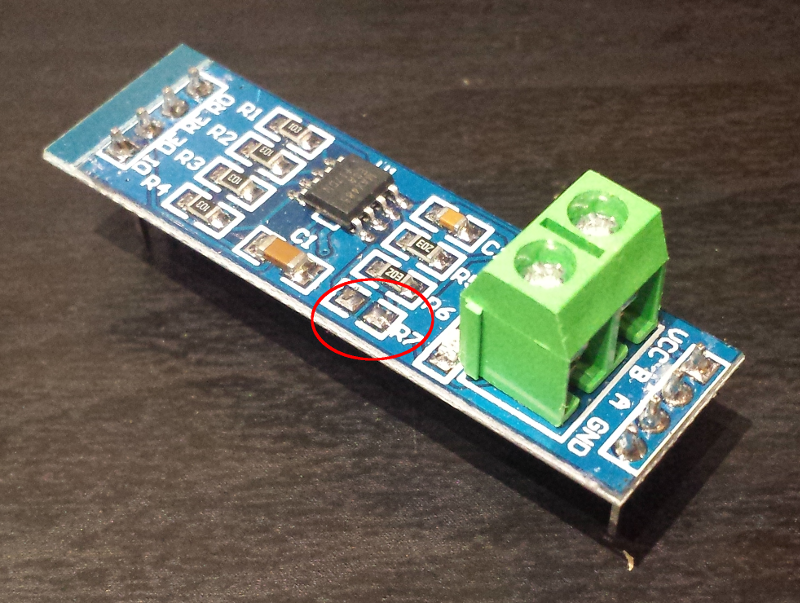
In this project, I chose to use a cheap RS-485 to UART adapter module based on the MAX485 chip (I got 5 pieces for 4 euros), its circuit diagram is as follows:
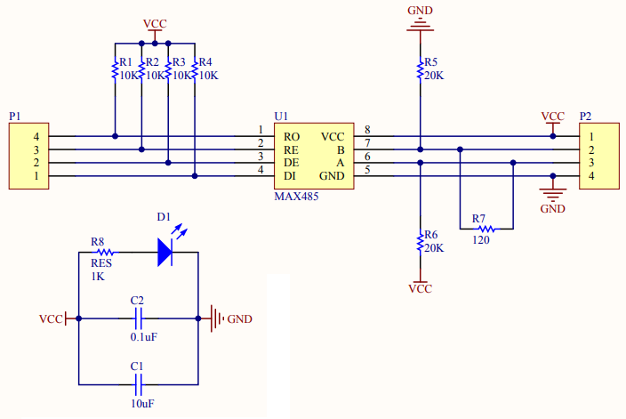
On this module the positive line is called A (note the pull-up to VCC), while the negative line is called B (note the pull-down to GND).
Note also that the module comes with a 120ohm termination resistor connected between A and B: this is generally a good thing when one uses two of these modules to implement a point to point connection, but in my case the intent is to plug the spy module in the “middle” of the bus, and middle nodes should not have termination resistor, so I removed the R7 resistor:
HW setup
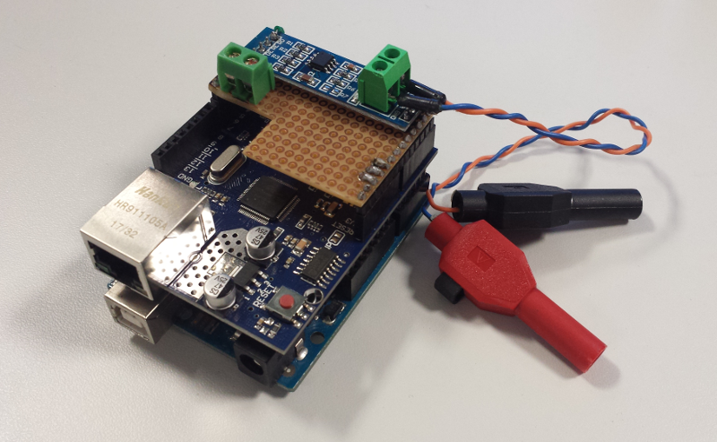
Here’s a view of the project HW setup:
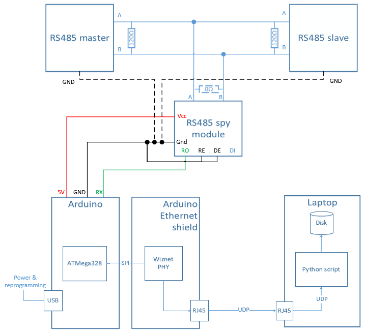
- the RS485 spy module connects to the RS-485 differential wire pair, and sends captured data bytes over its RO (Receiver Output) UART line to an Arduino.
- the RE signal is tied to GND, which permanently activates the spy module’s receiver (actually the signal is RE bar, so logic is inverted)
- the DE signal is tied to GND, which permanently deactivates the spy modules’ transmission driver, since it is not needed.
- the arduino is in charge of assembling the individual bytes into a message, adding a high-resolution timestamp, and sending the message as a UDP packet using the Ethernet shield
- the remote logging host (here a simple laptop) executes a python script listening for incoming UDP packets, and logging them in a file.
Note : I provisioned a GND connection (shown in dotted line above) just in case. Indeed, there is normally no need for connecting all GNDs of the modules communicating over the bus, the differential signalling over the wire pair should work in most cases without their GNDs being connected. But in some conditions, the local GNDs of the different modules may be shifted by a high enough voltage difference that the RS485 driver cannot properly interpret the differential signal anymore (i.e. the common mode rejection capability of the RS485 driver is not infinite… ). In this case, connecting all nodes GNDs together can get rid of the issue (and introduce new ones, but that is a story for another day). Anyhow, so far I did not have to connect the GND of the spy module to the GND of the other nodes.
Arduino board
I used an old Arduino Uno board I had laying around. For most projects I prefer small form factors (e.g. Arduino Pro/Mini/Micro), but on this project the need for an Ethernet shield left me no choice, and I had no space constraints anyway. Very few signals are needed:
- the 5V pin is used to supply the RS485 module
- the two GND pins next to the 5V are used as the ground reference for the RS485 module, and also to tie DE to inactive state and RE to active state
- pin 0 which carries the Arduino’s UART RX signal.
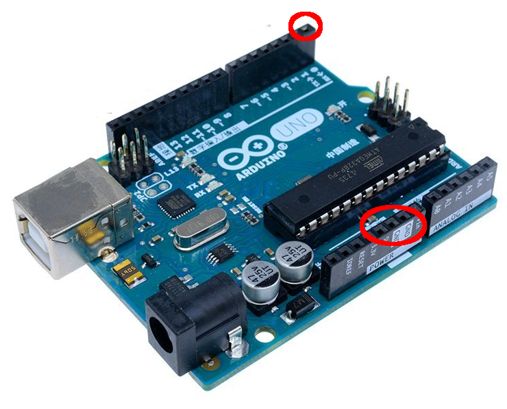
Other than this, the USB port is used to supply power to the Arduino, and reprogram it.
Ethernet shield
The Ethernet shield is relatively cheap, it can be found for around 10 euros. It embeds a Wiznet W5100 chip that includes an Ethernet MAC, PHY, as well as a hardwired TCP/UDP stack, and gets input data over an SPI interface.
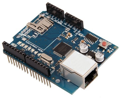
The W5100 support 100Mbit/s Ethernet (100BaseTX), but considering it reads it input data over a 4 MHz SPI interface, the actual achievable bandwidth is probably well below 4 Mbits/sec. For my project, this was not an issue since I had very small data bandwidth to monitor anyway (120 UART bytes, 50 times per second => 120 x 11 bits x 50 ~ 64kbit/sec)
The shield also embeds an SD Card read, which I had no use for in this project.
The shield conveniently provides headers to have access to many (not all) of the underlying arduino board signals, especially the UART RX signal that I needed to connect to the module
RS485 module integration
I went for a quick & dirty yet convenient solution to connect the RS485 module on top of the arduino+shield, by using a small piece of test PCB, soldering headers matching the arduino/shield header position, attaching the module on top of the PCB, and soldering the few required connections:
- VCC to Arduino’s 5V pin
- GND to Arduino’s GND pin
- RE and DE both connected to Arduino’s GND pin
Test setup
I build a very basic test setup to simulate the actual RS485 devices I needed to monitor, consisting of two Arduino Pro Mini boards, each one associated to its own RS485 module). One Arduino was programmed to send 120 bytes-messages over the bus at 50Hz, while the other Arduino was programmed to read the incoming characters (and do nothing with them)
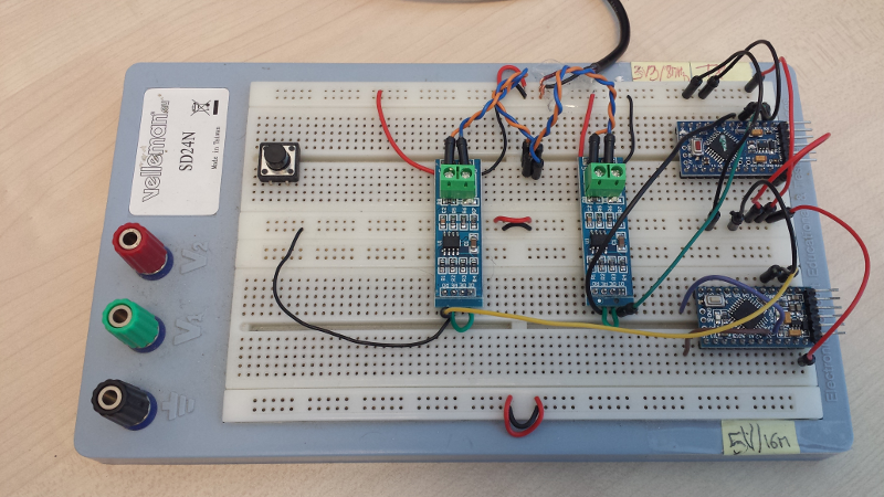
There is nothing special in the code beyond setting up the UART to operate at 1Mbps. Source code for both the test transmitter and the test receiver is archived here
Arduino SW
The code on the Arduino spy is very straightforward. First a few variables:
byte mac[] = {  0xDE, 0xAD, 0xBE, 0xEF, 0xFE, 0xED};
IPAddress local_ip(192, 168, 0, 40);
unsigned int localPort = 8888;
IPAddress remote_ip(255, 255, 255, 255);
char RecvBuffer[256];
EthernetUDP Udp;
- the MAC address is arbitrary
- the local IP address is also pretty much arbitrary, we are going to do UDP broadcast anyway
- the UDP port is arbitrary (just don’t select a value already used on your host)
- the destination IP is chosen to be 255.255.255.255 such that outgoing UDP packets are broadcasted to whoever listens on the correct port.
Configuring the Ethernet shield is as simple as using the associated libraries,
#include <Ethernet.h>
#include <EthernetUdp.h>
and calling this from the setup fonction:
Ethernet.begin(mac, local_ip);
Udp.begin(localPort);
Also in the setup, the baud rate of the UART is set to 1Mbit/s:
Serial.begin(1000000);
UART performance
My main concern initially was figuring out whether the Arduino Uno’s UART could support the 1Mbps baud rate, as this is a slightly unusually high value for a UART (and is not even a standard value, the closest would be 921 600 bauds). It turned out that 1000000 bit/s is working fine, with proper optimisations having been taken care of in the version of the UART library that ships with the Arduino release I used (1.8.1).
Still, 1 Mbps is 1MHz / 1 bit every µs, while the Arduino runs at 16 MHz. Receiving one character corresponds to 11 bits, so this means that one can execute an absolute maximum of 11x16 = 176 instructions and still keep up with reading incoming characters. That is not such a large amount of code that is possible to execute between character receptions. So I kept the core of the receiving code to its absolute minimum, reading the received character into a local buffer and incrementing the buffer index:
if (Serial.available() > 0) {
  RecvBuffer[recvIndex++] = Serial.read();
}
While characters from a given message are coming in, this is the only code that gets executed, and it keeps up just fine with receiving successive characters at 1 Mpbs, i.e. one character every 11 µs.
Detecting end of message
The next step was figuring out a way to determine that all characters from a message have been read : if the message size is known, one could just count characters, but this is not robust to any kind of error in character counting. So instead I went for the typical mechanism of detecting inter-frame gaps, i.e. detecting that during a given amount of time no new character has been received, and using this criteria to determine that a full message has been received.
The most convenient way I found to achieve this was using a timer, using the MSTimer2 library. The timer is created with a given period and a specific callback, in the setup part:
MsTimer2::set(MESSAGE_GAP_TIMEOUT_IN_MS, onTimer);
The timer is (re)started every time a new character is received within the timeout period:
MsTimer2::start();
At some point, the last character will come, and then the timer will finally expire, which will result in the callback being executed. In my case it boils down to just setting a flag:
void onTimer() {
  dumpData = true;
}
Dumping the received data
The main loop checks for this flag, and if it is set, builds a UDP packet with the content of the characters accumulated in the reception buffer. The very first thing is to create a timestamp, in microseconds, corresponding to when the message was received. The micro() function returns the current time in microseconds, and the timer period is subtracted from that, so that the timestamp corresponds to the moment when the final character of the message was received:
receiveTime = micros() - MESSAGE_GAP_TIMEOUT_IN_MS*1000;
The functions of the Ethernet library are very easy to use to build and send a UDP packet containing the buffered data :
  Udp.beginPacket(remote_ip, 8888);
  sprintf(receiveTimeString, "%015lu:", receiveTime);
  Udp.write(receiveTimeString, strlen(receiveTimeString));
  Udp.write(RecvBuffer, recvIndex);
  Udp.endPacket();
Programming the arduino
Code is programmed as usual using the Arduino IDE, over the USB cable. However, the reprogramming happens over the Arduino’s UART too, and having anything connected on the RX pin while reprogramming usually messes up with the reprogrammming procedure, and this time was no exception. I had to unplug the Ethernet shield & RS485 module from the Arduino Uno base for reprogramming to proceed successfully.
Source code
Source code for the arduino spy is archived here
Remote host data logging SW
On the remote host, I chose to use a simple Python script to listen for incoming UDP packets and log them into a file. This works fine for the very limited data bandwidth I have to monitor (i.e. 50 messages of 120 bytes per second), but would probably not be the right approach at higher datarates. Anyway, Python and its socket and logging libraries are so easy to use that I had a script working in no time.
The core of the receiving code boils down to :
sock = socket.socket(socket.AF_INET, socket.SOCK_DGRAM)
server_address = ('', LISTEN_PORT)
sock.bind(server_address)

	while True:
	data, address = sock.recvfrom(256)
Note: passing ‘’ as the IP address will listen on all local IP addresses, so no need to care which broadcast address to use.
The rest of the code is setting up the logging library, and formatting the received data. The logging library takes care of all the file size / historisation management, creating backup files and opening new ones as needed, which keeps the script very simple.
Source code is archived here
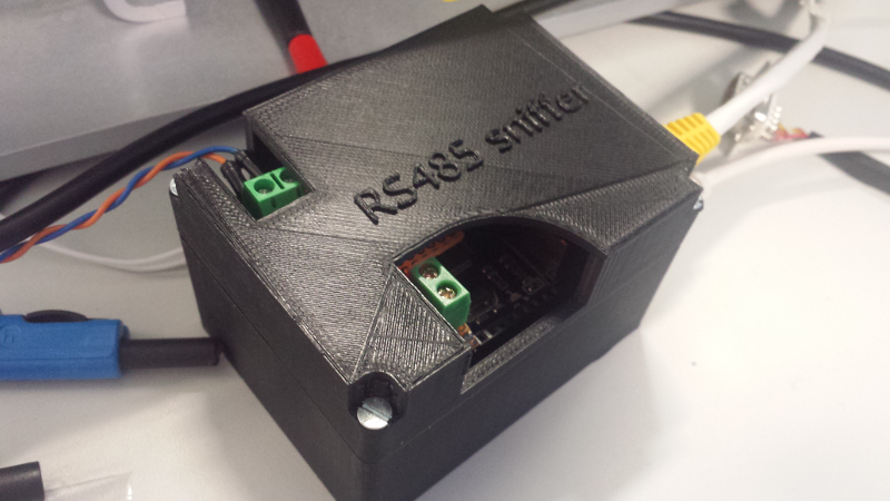
Enclosure
To make the spy a little more sturdy, but mostly to have some fun with Sketchup and my 3D printer, I created an enclosure for the Arduino/Shield/RS485 module stackup, with openings to give access to the RS485 signal headers.
Robustness testing
The initial intent of the project being to implement a 24/7 monitoring system, the next step was naturally to let the sniffer & remote logger run for a long time. The initial test of about 10 hours was performed overnight, with full logging of the received data, in a single file. It completely fine, but left the host PC in a state where it struggled with memory and CPU usage.
To lighten the load on the logging PC, I decided to do two modifications:
- configure the logging library to create a new logging file every few tens of MB of data, instead of letting the log file frow to several hundreds of MBs.
- as my usecase involved monitoring a bus where the same message gets sent over and over again (a health status if you will), instead of logging received data every time, I checked the received data against a predefined set of values, and only captured the timestamp and an “OK” status. If any value did not match, I logged the actual data bytes for later investigation. This simple change brought down the file size considerably, and eased the load on the logging PC.
This second version ran overnight with no issue, and with the logging laptop still alive and well the next morning. I also modified the test setup so that it would create a data error once in a while, to make sure the sniffer detected it :
17/07 23:27:45 Starting RS485 logger
17/07 23:27:45 starting up on  port 8888
17/07 23:27:45 000000041551212:OK
17/07 23:27:45 000000041572976:OK
17/07 23:27:46 000000041594744:OK
17/07 23:27:46 000000041616524:OK
17/07 23:27:46 000000041638300:OK
17/07 23:27:46 000000041660068:OK
17/07 23:27:46 000000041681848:OK
17/07 23:27:46 000000041703600:OK
17/07 23:27:46 000000041725376:OK
17/07 23:27:46 000000041747168:OK
17/07 23:27:46 000000041768920:OK
17/07 23:27:46 000000041790700:OK
17/07 23:27:46 000000041812460:OK
17/07 23:27:46 000000041834228:OK
17/07 23:27:46 000000041856008:OK
17/07 23:27:46 000000041877780:OK
17/07 23:27:46 000000041899560:OK
17/07 23:27:46 000000041921336:OK
17/07 23:27:46 000000041943100:OK
17/07 23:27:46 000000041964884:OK
17/07 23:27:46 000000041986644:OK
17/07 23:27:46 000000042008416:OK
17/07 23:27:46 000000042030212:OK
17/07 23:27:46 000000042051964:OK
17/07 23:27:46 000000042073732:OK
17/07 23:27:46 000000042095480:OK
17/07 23:27:46 000000042117276:OK
17/07 23:27:46 000000042139040:OK
17/07 23:27:46 000000042160808:OK
17/07 23:27:46 000000042182580:OK
17/07 23:27:46 000000042204288:!!!!!!ERROR!!!!!!:00,01,02,03,04,05,06,07,08,09,0a,0b,0c,0d,0e,0f,10,11,12,13,14,15,16,17,18,19,1a,1b,1c,1d,ff,1f,20,21,22,23,24,25,26,27,28,29,2a,2b,2c,2d,2e,2f,30,31,32,33,34,35,36,37,38,39,3b,3c,3d,3e,3f,40,41,42,43,44,45,46,47,48,49,4a,4b,4c,4d,4e,4f,50,51,52,53,54,55,56,57,58,59,5a,5b,5c,5d,5e,5f,60,61,62,63,64,65,66,67,68,69,6a,6b,6c,6d,6e,6f,70,71,72,73,74,75,76,77
17/07 23:27:46 000000042226060:OK
17/07 23:27:46 000000042247836:OK
17/07 23:27:46 000000042269600:OK
A few additional days of overnight testing confirmed that the logging is robust (as it should be, considering how straightforward the code is)