
Fusion360 survival guide
Below is a memo to myself for basic use of the Fusion360 CAD/CAM tool from Autodesk. There are plenty of resources/tutorials out there, but this just captures the bare minimum that I considered worthy of noting for my usecase, as a refresher for when it will have been months since I last used it, and I need to roll a quick and dirty design
Fusion360 is based on a monthly/yearly subscription fee, but is (at the time of writing) “free for startups, hobbyists, and enthusiasts”. My favorite modelling tool so far was Sketchup Make, but what brought me to Fusion360 is the fact that it has embedded support for CAM (Computer Aided Manufacturing), and more specifically has a post-processor that generates G-code for my Shapeoko.
It has integrated version management (very useful) and also implements many kinds of simulations, animation and renderings, and is heavily oriented towards cloud-based/collaborative work, but this not what matters the most in my case.
Installation
As of writing this, no native Linux version of Fusion360 is available, so I went and downloaded/installed the Windows version.
Basic shortcuts
Life is too short to click on the tools icons, the following shortcuts are must-know to get any decent productivity in Fusion360.
- S = command search
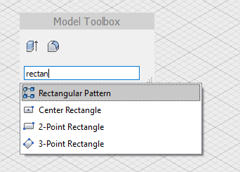
If there is a single shortcut to memorize it is this one: it opens up a search window, where you type in some words of the command you are looking for, and it will find all close matches:
Mouse buttons
- Shift + mouse middle-button = orbit view
- mouse middle-button = pan view
- Mouse wheel = zoom in/out
- double click mouse wheel = zoom to fit window
Keyboard shortcuts
- P = push-pull tool
- L = line tool
- R = rectangle tool
- C = circle tool
- D = dimension tool
Fusion360 workflow
Fusion360 has three main modeling principles:
- free-form modeling, using T-splines
- solid modeling, through a sequence of creating and combining basic primitive shapes and operations
- parametric modeling, using 2D sketches defining precise dimensions and relations between sketch elements.
- mesh modeling, importing pre-existing 3D objects and modeling around them.
For my needs I have been experimenting with parametric modeling mostly, and love the design approach of being able to define the critical dimensions and relations between parts, and let the modeller figure out other dimensions/shapes. The true power of Fusion360 is indeed in its workflow, that allows to go back to a previous version of the design, change one dimension somewhere, and NOT have to correct many other dimensions accordingly because the tool will take care of that given the predefined relations and constraints.
Parametric modeling basics
- Setting up axis orientation
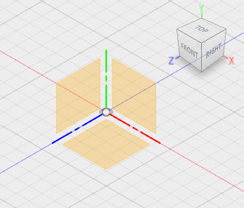
By default, the X/Y/Z axes are displayed with Y axis up:
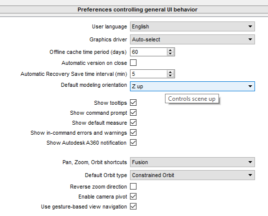
Even though this is arbitrary, I like to have my axis setup the same way as the physical axes on my Shapeoko, with Z being up, X being the width dimension, and Y being the depth. This can be set in the Preferences menu, with the “Z up” option in the Default Modeling Orientation setting
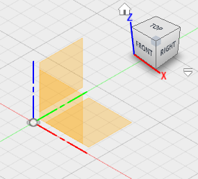
After modifying this and creating a NEW model, the axes are oriented the way I like:
-
A sketch can be drawn on a plane or a face. One of the 3 planes of the coordinate system can be used to kickstart a model, and later any face of an object can be used to define a sketch on it. In this example I chose the X/Y plane to start the sketch, the view automatically changes to orthogonal view of the X/Y plane:
-
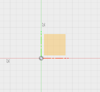
Then proceed to draw a quick and dirty outline of the target shape with the line tool, lengths and angles do not matter yet:
-
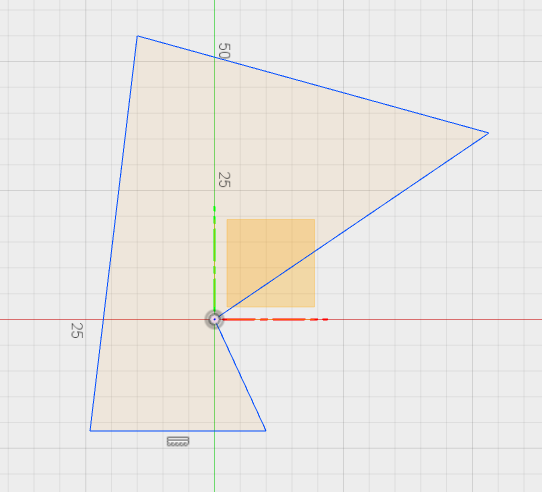
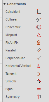
and then the real Fusion360 power comes in: the ability to apply constraints on/between edges:
- For example, here is the result of just
- clicking on the
Perpendicularconstraint then selecting the top and left lines - clicking on the
Horizontal/Verticalconstraint then selecting the bottom right line - clicking on the
Horizontal/Verticalconstraint then selecting the top line
- clicking on the
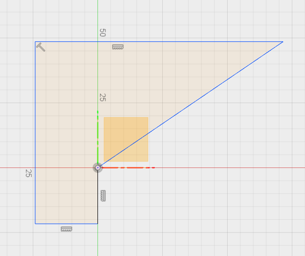
- Next up, setting specific dimensions on these edges. Here is the result after using the dimension tool (D shortcut), clicking on each of the three edges to specify their length:
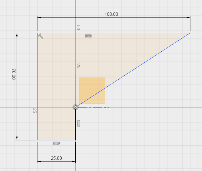
Note: at this point the sketch still has blue lines, which means some of its dimensions are still unconstrained. This is not necessarily a bad thing, it just shows what is locked and what is still free to be resized as a consequence of other model changes.
- the dimension tool can also be used to constrain the angle of the right part to e.g. 25°, by selecting the two edges forming the angle, and typing in the desired angle value, which results in:
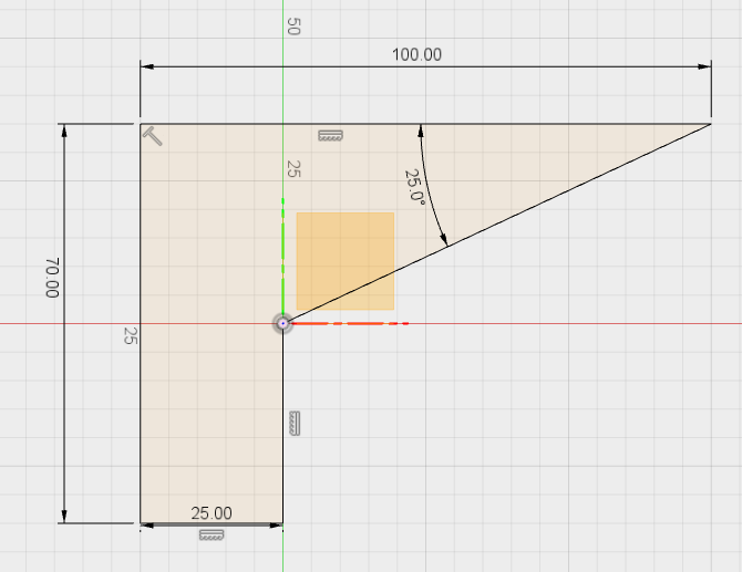
Note: the sketch is now fully black, which means it is fully defined/constrained.
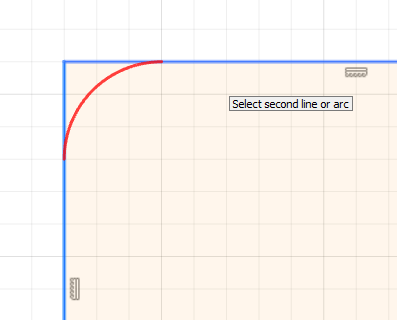
- Rounded corners are made with the
Fillettool from the sketch menu, just select two connected lines:
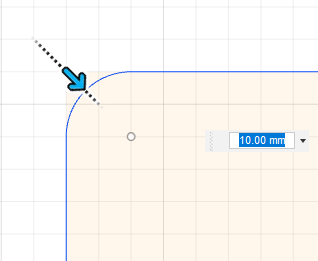
and select the fillet radius:
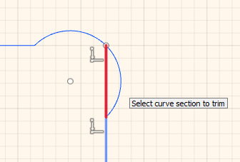
- The
Trimtool from the sketch menu is quite useful to clean-up a sketch to get just the right/useful lines:
- A useful feature (that I used all the time in Sketchup) is construction lines, serving as a reference only. In Fusion360, to draw a construction line, just draw a normal line, then right-click on it and toggle the
Normal/Constructionmenu item:
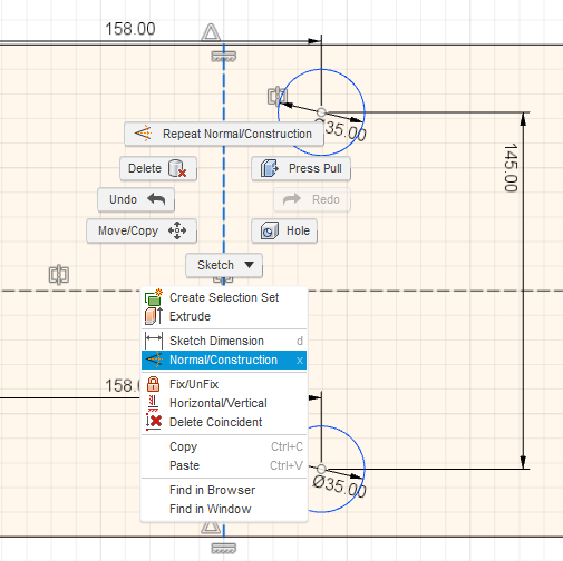
or just hit X for the same result.
- the
Press Pulltool can then be used to extrude the 2D sketch into a 3D shape:
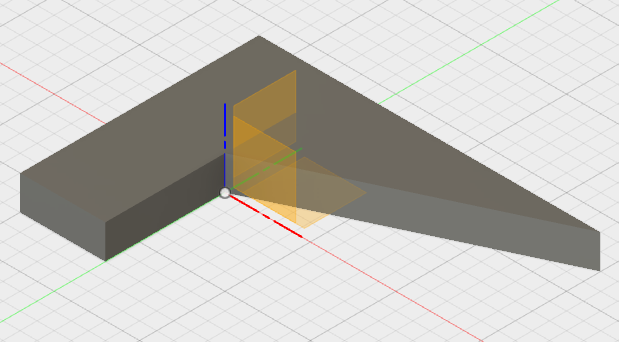
- I find the cross-section feature quite convenient, it is available in the
INSPECTmenu underSection analysis, just select a plane, and drag the section plane to the offset of interest:
CAM part
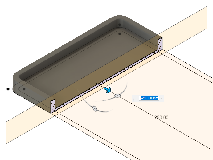
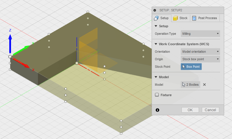
Once the 3D object is modelled, the CAM module of Fusion360 can be used to generate toolpaths. The first step is to setup the stock dimensions and zero point:
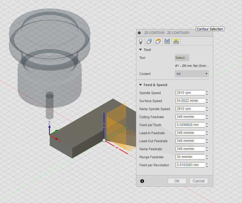
Then, a 2D or 3D milling operation must be created. For this simple case I chose a 2D contour. The first element to be selected is the endmill type, here I chose a square 6mm endmill:
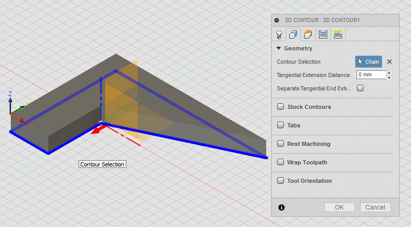
Then select the geometry to be machined, in this case I just want to cut out the piece from the stock so I select the contour of the base of the shape
And then setup the different milling heights (depths):
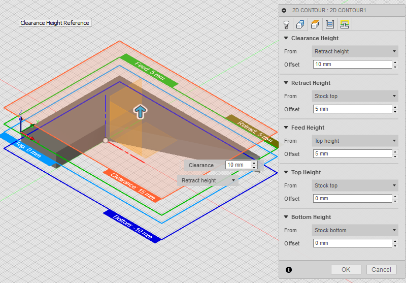
(Bottom Heights = stock bottom means it will mill through the full stock thickness, i.e. cut out the piece completely)
A very useful feature of Fusion360 is the ability to simulate/preview the toolpath execution:
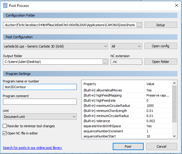
Finally, the post-process menu allows to configure & launch the G-code file generation:
Components
Components are the basic structuring entities of the model, they define a group of shapes/features that “belong” together. Most often a component corresponds to one solid piece of the modelled object. So it is good habit to create component from the beginning, to manipulate sub-assemblies of a given design more easily.